background image

10

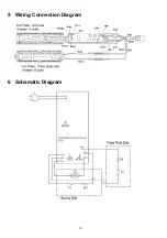
5 Wiring Connection Diagram

6 Schematic Diagram

Содержание EH-HW51

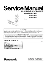
Страница 1: ...er Number PEWT1007A89CE Household Multi styling Straightener Model No EH HW11 EH HW32 EH HW51 ASIA TAIWAN TABLE OF CONTENTS PAGE PAGE 1 Warning 2 2 Specifications 2 3 Troubleshooting Guide 3 4 Disassembly and Assembly Instructions 5 5 Wiring Connection Diagram 10 6 Schematic Diagram 10 7 Exploded View and Replacement Parts List 11 ...

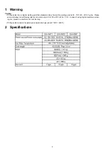
Страница 2: ...ng point is 50 70 F 30 40 C higher Please use a soldering iron with temperature control and adjust it to 750 20 F 400 10 C In case of using high temperature solder ing iron please be careful not to heat too long Pb free solder will tend to splash when heated too high about 1100 F 600 C 2 Specifications ...

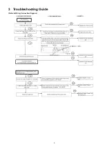
Страница 3: ...3 3 Troubleshooting Guide Refer to Wiring Connection Diagram ...

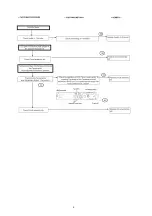
Страница 4: ...4 ...

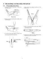
Страница 5: ...Phillips screw driver Plus driver 3 Push Shaft out by tiny shaped Phillips screwdrivers Plus driver and pull it out from the main body 4 Remove Pivot spring by gripping and pulling it out from the Main body 5 Remove 6 Screws for fitting Press plate side by Phillips screwdrivers Plus driver 6 Press plate cover at the Hook part by Slotted screwdriver Minus driver as shown in Figure below ...

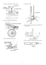
Страница 6: ...Spring 8 Remove Iron Plate of Heater B from Hook 9 Remove Slide Plate and Slide Spring 10 Take off Press Plate 11 Remove 2 Screws of the Housing side by Phillips screw driver Plus driver 12 Remove 6 Screws by Phillips screwdriver Plus driver ...

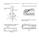
Страница 7: ...7 13 Remove Housing A from Housing B in Grip Case as fol lowing the drawing 14 Take off Iron Plate and Circuit assembly b k from Hous ing B ...

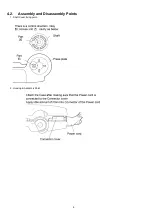
Страница 8: ...8 4 2 Assembly and Disassembly Points 1 Shaft Cover fixing point 2 Housing B Assembly Point ...

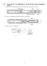
Страница 9: ...d Circuit arrangement points 1 Lead wire of Iron Plate Heater A assembly b k and Circuit assembly b k arrangement follows as below 2 Lead wire of Iron Plate Heater B assembly b k arrangement follows as below 3 Shaft cover must have a control direction ...

Страница 10: ...10 5 Wiring Connection Diagram 6 Schematic Diagram ...

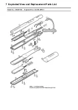
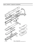
Страница 11: ...Model No EH HW11 Exploded View for EH HW11 7 Exploded View and Replacement Parts List ...

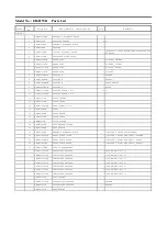
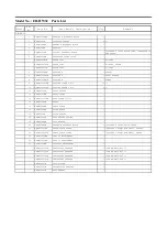
Страница 12: ... EHHW11T3012W TORX SCREW 3 0 12 1 14 EHHW11SHBW SHAFT 1 15 EHHW11PPBW PRESS PLATE 1 16 EHHW11SPBW SLIDE PLATE 1 17 EHHW11SSW SLIDE SPRING 1 18 EHHW11LBSW LOCK BUTTON SPRING 1 19 EHHW11LBBW LOCK BUTTON 1 20 EHHW11HBBW HEATER B ASSEMBLY BLOCK 1 INCLUDE 2 INSULATION TUBES 21 EHHW11PPCB1W PRESS PLATE COVER 1 INCLUDE 1 ALUMINUM SEAL TAIWAN 21 EHHW11PPCB7W PRESS PLATE COVER 1 INCLUDE 1 ALUMINUM SEAL KOR...

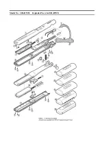
Страница 13: ...Model No EH HW32 Exploded View for EH HW32 ...

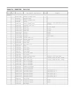
Страница 14: ... EHHW32PSSW PIVOT SPRING 1 12 EHHW32SCBW SHAFT COVER 1 13 EHHW32T3012W TORX SCREW 3 0 12 1 14 EHHW32SHBW SHAFT 1 15 EHHW32PPBW PRESS PLATE 1 16 EHHW32SPBW SLIDE PLATE 1 17 EHHW32SSW SLIDE SPRING 1 18 EHHW32LBSW LOCK BUTTON SPRING 1 19 EHHW32LBBW LOCK BUTTON 1 20 EHHW32HBBW HEATER B ASSEMBLY BLOCK 1 INCLUDE 2 INSULATION TUBES 21 EHHW32PPCBW PRESS PLATE COVER 1 INCLUDE 1 ALUMINUM SEAL OTHERS 21 EHHW...

Страница 15: ...Model No EH HW51 Exploded View for EH HW51 ...

Страница 16: ...2 1 14 EHHW51SHBW SHAFT 1 15 EHHW51PPBW PRESS PLATE 1 16 EHHW51SPBW SLIDE PLATE 1 17 EHHW51SSW SLIDE SPRING 1 18 EHHW51LBSW LOCK BUTTON SPRING 1 19 EHHW51LBBW LOCK BUTTON 1 20 EHHW51HBBW HEATER B ASSEMBLY BLOCK 1 INCLUDE 2 INSULATION TUBES 21 EHHW51PPCB1W PRESS PLATE COVER 1 INCLUDE 1 ALUMINUM SEAL TAIWAN 21 EHHW51PPCBW PRESS PLATE COVER 1 INCLUDE 1 ALUMINUM SEAL OTHERS 22 EHHW51C26BW CURL 26 ATTA...

Отзывы: