background image

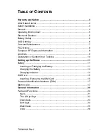
11.  CIRCUIT  DIAGRAMS

11.1.  Main  PCB (Baseband)

– 11-1 –

HINGE  I/F

D

AT

A[2]

DATA[1]
DATA[0]

WRQ

RDQ

POLY_EN

ADR[1]

D1
D0
/WR

SCLK[/RD]
SDOUT

SDIN[/CS]
SYNC[A0]

SPVSS

SPVDD

EQ3

HPOUT

HPOUT-L/MONO

HPOUTL

EQ2
EQ1

D

AT

A[3]

D

AT

A[4]

D

AT

A[5]

POL

YCLK

C2129

0.001u

C2106

10u

C2045

1u

C2046

1u

R2086 100K

R2087

R2029

22K

R

V2011

R

V2014

R

V2010

R2028    154K

C2053    0.1u

R

V2012

R

V2013

D2010

R2076

C2010

0p

C2107

0.1u

R2078          33K

R2070          33K

C2095     0.1u

R

V2024

A

VR-M1005C080MT

ABBG

R

V2020

A

VR-M1005C080MT

ABBG

R

V2019

A

VR-M1005C080M

TABBG

AVR-M1005C270MTABBG  X 3

AVR-M1005C270MTABBG

AVR-M1005C270MTABBG  X 2

AVR-M1005C270MTABBG  X 2

MAZS0750ML

C2193

0.1u

POL

Y_IRQ

POL

Y_RST

D

AT

A[6]

D

AT

A[7]

VIB_ON

SPOUT2

SPOUT1

D2

D3

D4

D5

D6

D7

EXT2

SPOUT2

SPOUT1

CLKI

EXT1

/IRQ

/RST

IFSEL

PLLC

VDD

VSS

VREF

U2011

YMU759B-QE2

U2003

RQ5RW28BA-TR

TB2002

CMT-1907-2797

V3V

VBAT

VBAT

VINT

V28

VANA

EPP2

26
27
28
29
30
31
32

16
15
14
13
12
11
10

25

24

23

22

21

20

19

18

17

1

2

3

4

5

6

7

8

9

L2011

82nH

L2013 2.2nH

C2098      0.047u

C2100      270p

R2080         33K

R2073         33K

R2079         150K

R2074

56K

R2075

100

C2101

0.0047u

1

GND
VDD

CE

VOUT

1
2

4
3

R2020    1K

C2016      2.2u

R2003    6.8K

R2038        30K

C2074      0.01u

C2072      0.1u

C2071      0.1u

C2066      0.1u

C2070      0.1u

C2052      0.1u

C2069      0.1u

C2044      0.1u

C2068      0.1u

C2067      0.1u

R2027    47K

V3V

VLOG

VANA

VINT

VINT

V3V

VRTC

VRTC

VANA

VSIM

VRF3 VCC 

±

 VCXO RF2V8 VBAT

EPOWER_SDA

DISP_RST

CUR_EN

TRI_R
TRI_B
TRI_G

ON_OFF
XO_ENE

EP_INT

RESET

EPOWER_SCL

RTC_OUT

TP2056

TP2042

φ

1.2

TP2041

1
2
3
4
5

32
33
34
35

26
27
28
29

21
22
40
39

20
19
41
58
59

12
11
49
18

14
47
13
48

50

51

10

44
43

55
56
17
16
45

53

9

52

30
25
24
23
15

7
4
1

60

2
3

57

5
6

54
46
38
36
31
61
62
63
64

42

8

37

CN2009

BTT-AJ3S-07-TF (LF)

CN2006

51338-0604

FL2001

MEA2010LC220T002

FL2002

MEA2010LC220T002

FL2003

MEA2010LC220T002

U2002

NC7SZ19P6X

R2008           0

R2007           0

R2060    1K

R2009         0

C2048      100p
C2049      100p

R2010         0

R2083

0

CAM32K

SPOUT1

RnW

RDQ

ADR[1]

CAM_A[2]

TEMP
BM_BB

CSCAM

SPOUT2

XO_ENE

CAM_IN

SW_EN

DISP_RST

EP_INT

SDIR

TEMP

TOPLED1

RECN
RECP
SDIR
RXIR
TXIR

CAM_INT
RESET

TP2116

TP2115

HCS 

±

 LCDX

HCS 

±

 APPX

GND-5

IN4
IN3
IN2
IN1

A

GND

E

Y0
VCC
Y1

OUT4
OUT3
OUT2
OUT1
GND-10

C2007

0p

C2008

0.1u

C2009

0.1u

C2011

0p

C2018

0p

C2019

0p

C2020

0p

C2056

10u

C2055

22u

C2028

0p

C2040

0p

C2039

2.2u

C2064

10u

R2037     2.2

C2063

10u

C2035

0p

C2036

0p

C2030

0p

C2031

0p

C2033

0p

R2151

100

R2150

100

C2134

0p

C2032 0.001u

C2054 0.1u

C2136

0p

C2022

0p

C2025

0p

1

2

1

2

4

3

4

3

R2016               100K

R2015               100K

C2135

0p

C2141

33p

C2109

27p

C2110

27p

C2120

47p

C2002

22p

C2037

22p

C2089

0p

C2012

0p

C2013

0p

C2142

33p

C2140

10u

C2001

10u

C2143

1u

R2152 2.2K

R2014 2.2K

R

V2027

R

V2015

R

V2028

AVR-M1005C270MTABBG

AVR-M1005C270MTABBG

AVR-M1005C270MTABBG

C2130

1u

C2096 0.1u

C2065 0.1u

R

V2021

A

VR-M1005C080MT

ABBG

TP2015

TP2018

TP2019

TP2024

TP2014

C2017

1u

C2059

2.2u

BT2001

XH414HIV01E

C2061

2.2u

C2058

2.2u

C2057

2.2u

TP2101

TP2106

TP2107

TP2108

TP2109

TP2110

TP2111

TP2112

TP2113

TP2114

C2060   2.2u

C2062   2.2u

D2021

MAZS0750ML

D2020

MAZS0750ML

C2111

0p

R2093

220

C2112

0p

C2113

0p

C2114

0p

C2023

0p

C2021

0p

C2014

0p

C2005

0.1u

C2006

0.1u

C2003

1u 16V

C2004

0p

D2003

BA

T60B

R2034

150K

R2043

47K

R2033

333K

R2035

100K

R2026

22K

R2036

100K

R

V2003

R

V2004

R

V2026

C2026

0.1u

C2015

0.1u

C2027

0.1u

VINT

±

 SD

V28

VINT

VBAT

VCHG

VBAT

VCHG

±

 SD

VCC 

±

 VCXO

RF2V8

VCHG

VBAT

CN2001

MQ208-2R

(+)

(–)

TP2045 TP2046

TP2012

TP2044

TP2030

TP2007

TP2058

TP2059

TP2060

TP2023

D2017

MAZS0750ML

D2022

MAZS0750ML

D2018

D2019

R

V2016

A

VR-M1005C120M

TAABG

R

V2017

A

VR-M1005C120M

TAABG

R

V2018

A

VR-M1005C120M

TAABG

MAZS0750ML

FL2007

12

BLM21PG221SN1D

MAZS0750ML

U2006

PMB6810  V1.83

5
4
3
2
1

6
7
8
9

10

IN1
IN2
IN3
IN4

GND-5

GND-10
OUT1
OUT2
OUT3
OUT4

1
2
3
4
5

10

9
8
7
6

GND-5

IN4
IN3
IN2
IN1

OUT4
OUT3
OUT2
OUT1
GND-10

5
4
3
2
1

6
7
8
9

10

6
5
4

3
2
1

DATA[3]
DATA[2]
DATA[1]
DATA[0]

DATA[7]
DATA[6]
DATA[5]
DATA[4]

7
6
5
4
3

1

2

±

 SD

L2010
2.2uH

R2031

0.1

D2002

BAT60B

NC-1
NC-2
NC-11
NC-12
NC-20
NC-32
NC-33
NC-34

SDA
SCL
VSSD-13
VSSD-26
VSSD-40
NC-41

IREF
BYP
VSSR

ON
VCXOEN
INTOUT

RESET

VDDRF

VRF1
VRF2
VRF3

VDDB

VCHS

VBATS

VDDPW

SW

FB

VINT

VANA

V3V

VRTC

VSIM

VSSA

VSSPW

VDDA

VDDCH

VCHC

1
2

11
12
20
32
33
34

35
31
37
36
23

5
6
8
9
18

7
4

10

39

24
3
22
30
21
25

16
15
13
26
40
41

19
38
14

19
28
27

17

C2047      0.047u

Q2006

RTQ035P02L02TR

1

2

3

4

4

3

AX

A
B

BX

TXON

PLLON

BAND 

±

 SEL

TXON 

±

 PA

AFC

EN

CLK

DA

PALEVEL

TXON 

±

 PA

AFC

EN

CLK

DA

PALEVEL

TXON

PLLON

BAND 

±

 SEL

AM 

±

 TRIG

TP2004

TP2011

TP2003

TP2002

TP2017 TP2036

TP2016 TP2037

TP2039

TP2010

TRI_G

TRI_B

CC06IO

A/A23/EX7IN

DSPOUT1/A22

A21/N/A

A20/N/A

A19/N/A

A18/N/A

A17/N/A

A16/N/A

A15/N/A

A14/N/A

A13/N/A

A12/N/A

A11/N/A

A10/N/A

A9/N/A

A8/N/A

A7/N/A

A6/N/A

A5/N/A

A4/N/A

A3/N/A

A2/N/A

A1/N/A

A0/N/A

A4

C3

C5

B5

A7

C6

B8

D6

C8

D7

D9

B9

C10

C9

B11

C11

D12

A12

C14

D13

E16

C17

E15

D17

MODE

ADR[22]

ADR[21]

ADR[20]

ADR[19]

ADR[18]

ADR[17]

ADR[16]

ADR[15]

ADR[14]

ADR[13]

ADR[12]

ADR[11]

ADR[10]

ADR[9]

ADR[8]

ADR[7]

ADR[6]

ADR[5]

ADR[4]

ADR[3]

ADR[2]

ADR[1]

ADR[0]

QRX/N/A
QR/N/A
IR/N/A
IRX/N/A
IT/N/A
QT/N/A
ITX/N/A
QTX/N/A

±

 OUT10/EX1IN/DSPIN1

HLDA/CC03IO/DSPIN0/T21IN

±

 OUT0/N/A

±

 OUT1/N/A

±

 OUT2/N/A

±

 OUT3/N/A

±

 OUT4/DSPIN0

±

 OUT5/CC17IO

±

 OUT6/T4IN

±

 OUT7/CAPIN

±

 OUT8/CC23IO

±

 OUT9/T7IN/EX3IN

AFC/N/A
RFSTR0/N/A
RFCLK/N/A
RFDATA/N/A
PAOUT/N/A

VDD1.0
VSS1.0
VDD1.1
VSS1.1
VDD1.2
VSS1.2
VDD1.3
VSS1.3
VDD2.0A
VSS2.0A
VDD2.0B
VSS2.0B
VDD2.0C
VSS2.0C
VDD2.1
VSS2.1
VDD2.2
VSS2.2
VDD2.3
VSS2.3
VDD2.4
VSS2.4
VDDRTC
VDDA
VSSRTC
VSSA

VDD
VSS
VDDT
VSST
VDDR
VSSR
VDDV
VSSV
VDDV2-E2
VSSV2-D2
VDDV2-E1
VSSV2-D1
VDDV2-D3
VDDX
VSSX
NGUARD
QGUARD
AGND

VREF/N/A
IREF/N/A

MRST
MTSR/SDA
SSCCLK/SCL

RXDD/RXD1
RFSD/EX4BIN
TFSD/T2IN
SCLK/T6EUD
TXDD/TXD1

TRIG 

±

 OUT/N/A

TDO/N/A
TMS/N/A
TDI/N/A
TRST/N/A
TCK/N/A
TRIG 

±

 IN/N/A

MON1/N/A
MON2/N/A

HOOK_KEY
TOPLED1
HS_DET
TRI_R
POLY_IRQ
SHUTDOWN

POLYCLK
KEYLED

OPDET

EPOWER_SCL
EPOWER_SDA

TXIR
TXDO

RXIR
RXDO

RECN
RECP

RESET

RDQ

WRQ

BHE

CSFLASH1
CSMSRAM
CSFLASH2

CUR_EN
CAM32K

CSCAM
POLY_EN

BM_BB
XO_ENE

RTC_OUT

POLY_RST

RnW

CAM_A[2]

KP0/T2EUD/EX0IN

KP1/CC06IOB
KP2/CC20IOB
KP3/CC16IOB

KP4
KP5

KP6/EX5IN

KP7/T7IN

KP8/CC22IOA
KP9/CC18IOA

CLKSXM/I2SWAO

LPAOUT1/I2SCAO

DSPOUT0/I2SDAO

READY/WAKEUP

±

 OUT12/N/A

±

 OUT11/CC19IO

RFSTR2/CC07IO
RFSTR3/CC21IO

CC00IO/T3OUT

CC01IOA/NMI/DSPOUT3

MMCROD/LPAOUT3/EX5BIN

RFSTR1/CC18IO

MMCCMD/CC2IO

MMCVDD/LPAOUT2

LPAOUT0/CC05TO

RXD1/EX1IN/T5EUD

RXDO

TXD1/CC04IO

TXDO

MICP1/N/A

MICP2/N/A
MICN2/N/A

EPN2/N/A
EPP2/N/A

RTCOUT/N/A

F32KX1/N/A
F32KX2/N/A

NC-T1

F131/26M

VCX 

±

 EN/T2UD/T3IN

CC02IO/HOLD/DSPOUT1

RFSTR4/EX2IN/CLK32K

RSTOUT/EX6IN/T3EUD/T5IN/A22

RESET 

±

 IN/N/A

EPN2
EPP2

SCL
SDA

MMCCLK/CC2CLK

MMCDAT

CLKOUT/VLK13/26M

RFREF/N/A
BREF/N/A
TBAT/N/A
VBAT/N/A
BTEC/N/A
TENV/N/A
TVCO/N/A

N3
N1

M2

N4

M4

L4

K2
K3

J14

U7

F16
F14
F15

G16
G14
G17

E17
F17

G15
H16

U5

J17
J15
J16

J2

B2
E4

A13
C13
N15
N14

R5
P5
B6
A6

D10
A11
B17
B16
U14
R13
H14
H17

U8
R7

N16
P17

T5

U2

T4

R2

K4

J1
L3

K1

M3

L1

G4

F3
E2

D2
E1
D1
D3

J4

H3

F4

R1
H4

H1

J3

P16
R16
U17

A1
C2
A2
A3
B3

NC-T2

NC-P4

NC-P14

NC-U1

NC-D14

NC-D4

T2

P4

P14

U1

D14

D4

T8

R10

U9

U10
R11

P9
R8

P10

T9

U13
T11
R12
R14
P13
P11
U11
T12
U12
T10

CCVZ

CCIOSW/T6OUT/T0IN/T6IN

CCRST/N/A

CCLK/N/A

CCIN/N/A
CCIO/N/A

EPN1/N/A
EPP1/N/A

VMIC/N/A

MICN1/N/A

CS0/N/A
CS1/N/A

CS2/CC02IOB/N/A

CS3/EX4IN/DSPIN0/T4EUD

CS4/DSPOUT2

RD/N/A

WR/N/A

BHE/CC00IOB

T14
P12
T16
T13
U15
R15
B1
C1
G1
G2

A15
C16
A17
D15
E14
B14
A16
C15

A14
B15
B12
B13
D11
C12
A10
B10
D8
A9
C7
A8
D5
B7
C4
A5

KP[0]
KP[1]
KP[2]
KP[3]
KP[4]
KP[5]
KP[6]
KP[7]
KP[8]
KP[9]

U6

R17
U16
T15

T6
K17
H15
K15
K16
R9
T17
P15
K14

M14
N17
P8

L17
M16

L14
M15

F1

H2
G3
F2
E3

R4
U3
U4

D16
L15

B4
P6

T1
T3
R6

P7
T7
M17
L16

R3

L2

P2
P1
N2
P3

M1

U2001

PMB7850E  V3.1F D12

DS2002

FA1114C-1205-TR

R2039

220

R2040

220

R2041

220

R2090

220

DS2003

FA1114C-1205-TR

DS2004

FA1114C-1205-TR

DS2005

FA1114C-1205-TR

DS2006

FA1114C-1205-TR

DS2007

FA1114C-1205-TR

DS2008

FA1114C-1205-TR

DS2009

FA1114C-1205-TR

DS2010

FA1114C-1205-TR

DS2011

FA1114C-1205-TR

DS2012

FA1114C-1205-TR

DS2013

FA1114C-1205-TR

DS2014

FA1114C-1205-TR

R2017

47K

RV2005

AVR-M1005C270MTABBG

R

V2006

A

VR-M1005C270MT

ABBG

RV2005

AVR-M1005C270MTABBG

RV2002

AVR-M1005C080MTABBG

VINT

R2021   1K

R2011

0

C2078   9p

C2081   9p

3  2

1

Y2001   MC-146A

4

DATA[0]
DATA[1]
DATA[2]
DATA[3]
DATA[4]
DATA[5]
DATA[6]
DATA[7]
DATA[8]
DATA[9]

DATA[10]
DATA[11]
DATA[12]
DATA[13]
DATA[14]
DATA[15]

CSFLASH1
CSFLASH2

DATA[15]
DATA[14]
DATA[13]
DATA[12]
DATA[11]
DATA[10]

DATA[9]
DATA[8]
DATA[7]
DATA[6]
DATA[5]
DATA[4]
DATA[3]
DATA[2]
DATA[1]
DATA[0]

/CEF1
/CEF2

MODE

VCCQ

VCCF

/WE

/OE

NC-H6

/WP[ACC]

I/O15
I/O14
I/O13
I/O12
I/O11
I/O10

I/O9
I/O8
I/O7
I/O6
I/O5
I/O4
I/O3
I/O2
I/O1
I/O0

NC-G1
NC-G9

NC-G10

NC-H1

NC-H10

NC-M5
NC-M6
MC-P1

NC-P10

NC-M1
NC-M2
NC-M3

MC-M8

NC-M9

NC-M10

NC-N1
NC-N2
NC-N9

NC-N10

G1
G9
G10
H1
H10
M5
M6
P1
P10
M1
M2
M3
M8
M9
M10
N1
N2
N9
N10

E6
L6
K5
D6
J3
H6
J2
G6
J8
L8
J7
K7
L5
K4
J4
L3
K8
H7
L7
J6
J5
L4
H4
K3

NC-G5
NC-H8

G5
H8

K2
E5
D4
E4
H2

G2

F2
E2

G3

F3
E3

D3
D7

F7

G7
D8

E8
F8

G8

E9
H9

G4

F4
E7
F6
F9

NC-J9
/CEM
/RESET
/LB
/UB
A0
A1
A2
A3
A4
A5
A6
A7
A8
A9
A10
A11
A12
A13
A14
A15
A16
A17
A18
A19
A20
A21

H5
H3
K9

IC
VSS-H3
VSS-K9

A1

A10

C5
C6
D2
B1
B2
B9

B10

C1
C2
C3
C8
C9

C10

NC-A1
NC-A10
NC-C5
NC-C6
NC-D2
NC-B1
NC-B2
NC-B9
NC-B10
NC-C1
NC-C2
NC-C3
NC-C8
NC-C9
NC-C10

VCCM

RY[/BY]

F5

K6

J9

D5

D0/N/A

D1N/A
D2N/A
D3N/A
D4N/A
D5N/A
D6N/A
D7N/A

D8/CC20IOA
D9/CC16IOA

D10
D11

D12/EX5IN

DATA[13]

D14/CC22IOB
D15/CC18IOB

DATA[0]
DATA[1]
DATA[2]
DATA[3]
DATA[4]
DATA[5]
DATA[6]
DATA[7]

DATA[0 - 15]

ADR[0 - 22], MODE

V3V

VINT

VINT

±

 SD

MODE

RESET

ADR[1]

TP2038

U2008

MC-26426312F9-E80X-CR2

ROM/RAM

128MF (16M X 2)/32MS

WRQ

RDQ

ADR[0]

BHE

ADR[1]
ADR[2]
ADR[3]
ADR[4]
ADR[5]
ADR[6]
ADR[7]
ADR[8]
ADR[9]

ADR[10]
ADR[11]
ADR[12]
ADR[13]
ADR[14]
ADR[15]
ADR[16]
ADR[17]
ADR[18]
ADR[19]
ADR[20]
ADR[21]
ADR[22]

CSMSRAM

MODE

VANA

VANA

R2094   1K

C2137      0.1u

C2091

0.1u

C2144        0p
R2141         20K

C2092

0.1u

C2138      0.1u

FL2008

BK1005HM102-T

1

4

1

3

2

2

5

R2046

2.2K

MK2001

SP0102ZE3-PB-4

TP2117 TP2057

TXDO

RXDO

HOOK_KEY

HS_DET

VIB_ON

FL2010

EMIF03-SIM01F2

SW_EN

EPN2

HPOUTL

D2004          MA2SD1900L

D2027

MAZW068H0L

D2026

MAZW068H0L

D2025

MAZW068H0L

D2024

MAZW068H0L

D2023

MAZW068H0L

R2145 4.7K

R2147

100

R2146

R2048 4.7K

R2006 100K

R2142

20K

R2143

20K

C2041    0p

C2148 0.1u

C2043    0p

TP2026

TP2027

TP2028

TP2029

TP2034

TP2033

TP2032

TP2031

C2024    0p

C2042    10p

R2144 330K

R2012 100K

R2024 100K

R2019 100K

D2015

EMZ6.8ET2R

D2005          MA2SD1900L
D2006          MA2SD1900L
D2007          MA2SD1900L
D2008          MA2SD1900L
D2009          MA2SD1900L

VANA

SHUTDOWN

U2012

LM4809LQX/NOPB

2
3

3

1

2

1
4

OUT VDD

GND

V28

E2001

EW-6671-FT

S2022

EVQP7D01K

1

3

2

1

3

2

1

3

2

1

3

2

1

3

2

1

2 3

5

4

VOUT

VIN1

BYPASS

GND-4

GND-9
VDD
VOUT2
VIN2
SHUTDOWN

ON_OFF

VPAT

TP2050

TP2051

TP2052

TP2053

TP2054

TP2055

TP2118

TP2119

TP2120

TP2121

TP2122

TP2123

TP2124

CGROUN

EGND

KEYLED

Q2008

2SD19790VL

1

2

3

R2018

4.7K

4

1

3

2

4

1

3

2

4

1

3

2

4

1

3

2

R2091

220

4

1

3

2

R2092

220

4

1

3

2

KP 

±

 [0]

KP 

±

 [1]

KP 

±

 [2]

KP 

±

 [3]

KP 

±

 [4]

KP 

±

 [5]

KP 

±

 [6]

KP 

±

 [7]

KP 

±

 [8]

KP 

±

 [9]

KP 

±

 [0]

KP 

±

 [1]

KP 

±

 [2]

KP 

±

 [3]

KP 

±

 [4]

KP 

±

 [5]

KP 

±

 [6]

KP 

±

 [7]

KP 

±

 [8]

KP 

±

 [9]

UNR9210J0L

Q2002

VBAT

S2021

S2001

S2007

S2013

S2002

S2008

S2014

S2019

S2003

S2009

S2015

S2004

S2010

S2016

S2005

S2011

S2017

S2006

1

2

3

4

5

6

7

8

0

9

S2012

S2018

S2020

END/PWR

SEND

P.B.

CNT

SOFT

R2088            0

VINT

VINT

VINT

VSIM

VSIM

VINT

VINT

C2104     10u

C2146

0.1u

R2081          2.2K
R2082          4.7K

VCC

RSTOUT

RSTIN

CLKOUT

GND

DATAIN
VCC
DATAOUT
VCC

A2
A3
B1
B2

C3
C2
C1
B3

OE

A
B
GND

U2013

TC7SB66FU (TE85L.F)

VANA

CN2008

DF12B(3.0)-14DS-0.5V(81)

CN2005

HSJ2055-019070

1
2

3
4
5
6
7
8
9
10
11
12
13
14
15
16

5
1
3

2
4

HOOCK 

±

 KEY

GND
HS 

±

 RX

HS 

±

 TX

HS 

±

 DET

Key LED

Key I/F

PHF I/F

SIM/Vibrator

Interface

MIC

Memory

32KHz X'tal

Baseband

LSI

Power

Control IC

Melody IC

Main

Upper

Interface

Batt CN

DC Jack

Charge

Содержание EB-X400

Страница 1: ...paration 45 MHz 95 MHz RF Channel Bandwidth 200 kHz Number of RF channels 174 374 Speech coding Full rate Half rate Enhanced Full rate Operating temperature 10 C to 55 C Type Class 4 Handheld Class 1 Handheld RF Output Power 2 W maximum 1 W maximum Modulation GMSK BT 0 3 WAP GPRS WAP 2 0 GPRS Class 8 Connection 8 ch TDMA Voice digitizing 13 kbps RPE LTP 13 kps ACLEP 5 6 kps CELP VSLEP Transmission...

Страница 2: ...1 1 2 Structure of the Manual 1 1 1 3 Servicing Responsibilities 1 1 2 GENERAL DESCRIPTION 2 1 2 1 General 2 1 2 2 Features 2 1 2 3 Handportable Main Kits 2 1 3 OPERATING INSTRUCTIONS 3 1 3 1 General 3 1 3 2 Controls and Indicators 3 1 3 3 Liquid Crystal Display 3 2 3 4 Text Entry Edit 3 2 3 5 Menu Structure 3 3 4 TECHNICAL SPECIFICATIONS 4 1 4 1 Tx Characteristics 4 1 4 1 1 Frequency Error 4 1 4 ...

Страница 3: ...ion 7 1 7 2 Lead Free PbF solder 7 1 7 3 External Testing 7 1 7 3 1 General Information 7 1 8 SOFTWARE DOWNLOAD ADJUSTMENT PROCEDURES 8 1 8 1 FlashTool update and operation guide 8 1 8 1 1 Introduction 8 1 8 2 FlashTool update 8 1 8 3 Software upgrade procedure FlashTool operation by using SPK file 8 2 8 3 1 8 4 1 Select SPK file 8 2 8 3 2 COM port set up 8 4 8 3 3 Start download 8 5 8 4 RF Calibr...

Страница 4: ... Band 10 2 11 CIRCUIT DIAGRAMS 11 1 11 1 Circuit Diagram of Main PCB Baseband 11 1 11 2 Circuit Diagram of Main PCB RF Band 11 2 11 3 Circuit Diagram of Upper Face PCB 11 3 11 4 Circuit Diagram of Hinge PCB 11 4 11 5 Circuit Diagram of SIM PCB 11 5 12 LAYOUT DIAGRAMS 12 1 12 1 Layout Diagram of Main PCB 12 1 12 2 Layout Diagram of Upper Face PCB 12 2 12 3 Layout Diagram of Hinge PCB 12 3 12 4 Layo...

Страница 5: ...Mobile Telephone system operating on GSM Digital Cellular Networks 1 2 Structure of the Manual 1 3 Servicing Responsibilities The manual is structured to provide service engineering personnel with the following information and procedures 1 General and technical information provides a basic understanding of the equipment kits and options together with detailed information for each of the major comp...

Страница 6: ...h includes Full Rate Half rate and Enhanced Full Rate EFR speech codec 2 Dual Band E GSM 900 and GSM 1800 operation 3 Tegic T9 Text Entry 4 Voice Ringer 5 Desktop Hand free function comprising integral echo cancellation and noise suppression 6 Wireless Application Protocol WAP Browser 7 Backup Battery 8 Downloadable polyphonic melody ring tones 9 Clock Calculator and Currency Converter 2 3 Handpor...

Страница 7: ... Display One Push Auto Open button Press to open the handset Left soft key Asterisk key Charging Connector Camera lens Self Portrait mirror Use to frame self portrait camera shots Multi Function key Camera Shutter Alert mute Send key To answer a call or to make an outgoing call 1 key Vodafone mail key Press and hold to call Vodafone mail Microphone Infrared Port Illumination Light Charging Indicat...

Страница 8: ...nput mode Shift Hold Input mode change Hold Input mode change Space Hold Line feed Delete text Hold Delete all characters Space Hold Line Feed Hold Line Feed NOTE Displayed characters of T9 vary depending on the selected Input language 3 3 Liquid Crystal Display The telephone handset has a graphical chip on glass display The following icons are available Figure 3 2 Liquid Crystal Display 1 Hold Ch...

Страница 9: ...at Cell Broadcast Settings Memory status Camera My Media Pictures Sounds Shortcuts Text templates Memory status Settings Profiles Sound Vibration Alert Display Language Data connections GSM network Calls Security Time and date Any key answer Keyguard Calendar Contacts Contacts list Add contact Call log Speed Dial list View groups Advanced Service numbers Browser PANASONIC BOX ...

Страница 10: ...dulation Offset from Centre Frequency kHz Maximum Level Relative to Carrier dB Offset from Centre Frequency kHz Maximum Level dBm 100 0 5 200 30 250 33 400 60 600 to 1800 60 4 1 4 Output RF Spectrum due to Switching Transients E GSM 900 GSM 1800 400 19 22 600 21 24 1200 21 24 1800 24 27 Measurement conditions for output RF spectrum measurements Frequency Span 0 Hz Measurement Bandwidth 30 kHz Vide...

Страница 11: ...100 kHz 300 kHz 36 36 500 MHz to 1 GHz 0 to 1 MHz 100 kHz 300 kHz 36 36 1 GHz to 12 75 GHz 0 to 10 MHz 100 kHz 300 kHz 30 30 1 0 1 710 GHz Excl relevant TX band 10 MHz 300 kHz 1 MHz 30 E GSM 880 MHz to 915 MHz 30 MHz 3 MHz 3 MHz 30 36 1 710 1 785 GHz DCS 1710 MHz to 1785 MHz off trom edge of and the Rx bands relevant Tx band 30 1 785 12 75 GHz 925 MHz 960 MHz 1805 MHz 1880 MHz Relevant TX band 1 8...

Страница 12: ...onditions HT Static Conditions Minimum No of samples Minimum No of samples Minimum No of samples Minimum No of samples Test Limit error rate Test Limit error rate Test Limit error rate Test Limit error rate TCH FS FER 4 478 α 13 400 0 122 α 164 000 class Ib RBER 0 32 α 1 500 000 0 41 α 20 000 000 class II RBER 8 333 600 000 7 5 24 000 9 333 30 000 2 439 8 200 Channels Propagation conditions TU hig...

Страница 13: ...SM 900 GSM 1800 FR 600 kHz to FR 800 kHz FR 800 kHz to FR 1 6 MHz FR 1 6 MHz to FR 3 MHz 915 MHz to FR 3 MHz FR 3 MHz to FR 980 MHz FR 600 KHz to FR 800 KHz 1785 MHz to FR 3 MHz 835 MHz to 915 MHz 980 MHz to 1000 MHz 100 KHz to 835 MHz 1000 MHz to 12 75 GHz 100 KHz to 1705 MHz 1705 MHz to 1785 MHz 1920 MHz to 1980 MHz 1980 MHz to 12 75 GHz 70 70 80 90 90 113 113 90 90 _ _ _ _ 70 70 80 87 87 113 10...

Страница 14: ...solation between 900MHz and 1800MHz The impedance of these two filters output is 150 Ω balanced EGSM900 DCS1800 The input receiving signals into the LNAs coming from the SAWs provide out band reflection However the receiver is a direct conversion type there is no need to concern about the image frequency blocking problem Figure 5 1 RF Block Diagram 5 TECHNICAL DESCRIPTION U301 TCXO module MAA A 26...

Страница 15: ...h the control line PALEVEL Harmonics in the PA output signal are attenuated by low pass filters inside the Front End Module Synthesiser Description A synthesiser is provided in transceiver IC U101 The internal VCO operates from 3 42 GHz to 3 98 GHz thus it is equivalent to 2 and 4 times of the DCS and EGSM frequencies The registers counters and phase detectors for this synthesiser are included in ...

Страница 16: ...Clock Generation Power Management MMCI Multicore Debug Support GPT1 GPT2 Watchdog CAPCOM SSC RTC Osc ASC 0 ASC 1 DSP Timer1 I2 S DSP Serial Comm Interface DAI Cipher Unit P ROM P RAM Y RAM X RAM X ROM Viterbi HW Accelerator Switch matrix Battery Temp Measurement TAP Controller JTAG Boundary Scan MUX DAC ADC ADC ADC DAC DAC GMSK Modulator Baseband Filter Cordic Processor Voiceband filters RX and TX...

Страница 17: ... and YEAR Daily Weekly Alarm control Time constant interrupt generator High accuracy time correction control Acoustic Components Desktop handsfree DTHF operation is supported using a DTHF speaker located in the bottom of the handheld unit Ringing tones are also output from this speaker Headset with remote switch A headset with remote control is available as an accessory This arrows the user to rec...

Страница 18: ...ry data bus is 16 bit wide The SRAM utilizes the BHEQ signal to support both 8 and 16 bits access for more efficient use The memory interface of the U2001 E Gold V3 supports 1 8 V or 2 6 V operation allowing flexibility on the choice of memory components EB X400 adopted 2 6 V operation because the operation voltage of memory is 3 0 V operation The memory interface voltage level is selected by conn...

Страница 19: ... SWCLK PLL Clock Switch Bit CLKAEN CLKANA Enable Bit SXMEN Coprocessor clock enable SX52M Coprocessor clock switch AFCEN AFC Enable Bit CPUH Enables 52 MHz operation of the CPU and serial interface CPUPRE 2 0 CPU Clock Prescale Factor AFC32KEN AFC clock enable during ECO eco sleeep mode 13 26MHz_IN Configure the CGU for the operation with either 13 MHz or 26 MHz input CGURST Clock Generation Uint ...

Страница 20: ...ng erroneous conditions and exceptions that arise during the program execution Hardware traps always have highest priority and cause immediate system reaction The software trap function is invoked by the TRAP instruction which generates a software interrupt for a specified interrupt vector For all types of traps the current program status is saved in the system stack Interrupt Processing via the P...

Страница 21: ...CL games refers to the below table Keypad assignments Column 1 Column 2 Column 3 Column 4 Column 5 Column 6 KP0 KP1 KP2 KP3 KP4 KP5 Row 0 Left Up 7 4 1 KP6 Game C Game A Row 1 Send Center 0 8 5 2 KP7 Fire Fire Row 2 Right Down 9 6 3 KP8 Game D Game B Row 3 Soft_1 Soft_2 Shutter KP9 Bottom E Gold V3 pin name Ball EB X60 use Description HLDAQ CC03IO DSPIN0 T2IN U7 SDIR IrDA sensor enable disable T_O...

Страница 22: ...nder adverse environmental conditions For this purpose an 8 bit CRC byte is appended to each command word Only if the CRC has been verified by U2006 the transferred command will be executed Correct reception and execution of the transmitted command can be verified by E Gold by reading back the transmitted CRC byte Timer Watchdog Timer The MCU general purpose timer blocks contain 9 16 bit timers an...

Страница 23: ...es of all output signals at this time One timing compare value and the corresponding TRIG 25 0 signal values are called timing event The RAM operates like a FIFO The TDMA Compare Unit compares the last timing compare value of the FIFO with the TDMA counter value When both values are identical the corresponding output values for TRIG 25 0 are read out of the RAM and taken over by the external signa...

Страница 24: ... cosine shape will be used as a starting basis of the ramp shape Figure 5 4 Functional structure of the baseband Uplink Downlink path Figure 5 5 Raised and fall cosine for the PA ramp TOUT i GAIM_DATA PAOUT 0 V GAIM_CLK RFSTR 5 trig_start ramp up 1 2 3 15 16 17 18 30 31 32 ramp down DAC CLK 26 MHz GSM 1900 GSM 900 1800 ENA DAT I Q DAC DAC DAC ADC ADC ADC OAK SSC MMC I C I S DAI JTAG IrDA ASC C166S...

Страница 25: ...e requirements for the low pass filter are considerably reduced compared to a pulse width modulated output or a pulse number modulated signal with unequal distribution In this example which uses 11 bits the lowest frequency component in the spectrum of any E Gold V3 PNM sequence is 6 35 kHz and has an effective amplitude of less than 1 LSB Audio E Gold V3 provides the analogue interface for the di...

Страница 26: ...EB X400 has values of electrical volume for A D calibration as follows Battery voltage VBAT1 VBAT2 Battery temperature TBAT1 TBAT2 Environment temperature TENV1 TENV2 5 2 4 CPU MEMORY EB X400 uses following memory configuration 128 Mbits Flash memory organised as 4M x 16 4M x 16 36 Mbits RAM organised as 128k x 32 Internal SRAM 2M x 16 mobile RAM EB X400 uses Dual operation Flash memory mobile RAM...

Страница 27: ...0000 Data register 01C1 0000 These registers are write access only 5 2 6 IrDA The IrDA module is mounted on the upper unit PCB EB X400 supports IrDA file transfer and object exchange but does not support IrDA dial up In a special asynchronous mode of U2001 E Gold V3 the ASC supports IrDA data transmissions up to 115 2 KBaud with fixed or programmable IrDA pulse width An autobaud detection unit det...

Страница 28: ...control and data interface to the U2011 is provided by connecting the U2001 to the lower byte of the parallel data bus Furthermore a 13 MHz clock output and a IRQ input must be provided Block Diagram Figure 5 9 IrDA Block Diagram Figure 5 10 Melody Block Diagram PD BUS IrDA Support IrDA Support ASC1 Controller ASC0 Controller Autobaudrate Block Pinmux Block Pinmux Block Autostart Block SIM Card IF...

Страница 29: ...eaker amp The U2011 features two SW controllable outputs intended for vibrator If the synchronization features of the SMAF format should be 100 utilized these outputs should be used to drive the vibrator 5 2 8 AUDIO Receiver Because U2001 runs off 2 7 V a high impedance ceramic speaker will not satisfy user requirements for volume therefore a lower impedance dynamic type is used GSM requires that ...

Страница 30: ...nitor battery usage The Power Management Block consists of 5 parts as follows 1 Power Source 2 Power On Off Control 3 Power Source Failure detection 4 Voltage Regulation 5 Battery Charging Monitoring Lithium ion Li cells are used in the EB X400 battery pack These cells have improved gravimetric and volumetric energy densities compared to that of Nickel Metal Hydride Ni MH cells EB X400 uses power ...

Страница 31: ...witching type AC adaptor or DC adaptor The Switching type AC adaptor complies with the worldwide voltage regulations Input Output Voltage Voltage Current AC Adaptor Switching type 100 240 V 5 8 V 650 mA Figure 5 13 Power supply block diagram E Power ...

Страница 32: ... up for the first time after a battery has been inserted the high level on pin ON may only be caused by a power on push button having been pressed If a charged battery is inserted into the handset the RTC block on E Gold V3 will be activated if the supply voltage is above 2 50 V 0 4 V The RTC voltage regulator is automatically switched on without power on trigger The power on sequence of E Power r...

Страница 33: ...band power supply for Digital core V_SD Voltage 1 83 V 0 06V Current 180 mA max Dropout 100 mV max load max VINT Power supply for E Gold V3 I O VINT Voltage 2 62 V 0 10 V Current 50 mA max Dropout 150 mV max load max V3V Power supply for mobile SRAM and polytone IC V3V Voltage 2 85 V 0 10 V Current 50 mA max Dropout 150mV max load max VANA Power supply for analogue part VANA Voltage 2 39 V 0 09 V ...

Страница 34: ... its clamshell style case is open or closed The Hall IC detector E2001 has a low output when clamshell is closing and high when it is opening The open close status is monitored by the I O terminal P8 of U2001 E Gold V3 The MCU can generate an interrupt for Open or Close detection Remote Switch function of PHF EB X400 has the feature of remote switch of PHF This PHF is same as EB GD87 It is shorted...

Страница 35: ...erter of E Power changes the operation mode from PWM to PFM to save battery power Maximum current delivery is 50 mA The following diagram shows the relations between UI condition state transition verses System sleep control restrictions Location Luminous Colour Pattern Lighting interval Incoming Call Purple 50 Duty ON 480 msec OFF 480 msec In Voice Call Blue 50 Duty ON 1 sec OFF 1 sec Missed call ...

Страница 36: ... LCD Bklt Off Companion IC Camera Mode LCD Full Colour LCD Bklt Bright Companion IC LCD Bypass Access LCD Full Colour LCD Bklt Off Companion IC LCD Bypass Access LCD Full Colour LCD Bklt Off Companion IC LCD Bypass Access Active LCD Stby LCD Bklt Off Companion IC Power Save Mode LCD Stby LCD Bklt Off Companion IC Power Save Mode LCD Stby LCD Bklt Off Companion IC Power Save Mode LCD Stby LCD Bklt ...

Страница 37: ...Gold V3 13 PALEVEL Power control voltage for PA PAOUT of E Gold V3 14 TEMP Environment temperature signal TENV of E Gold V3 15 BM_BB System clock 26 MHz F13 26 of E Gold V3 0 5 Vpp min DC coupled 16 AM_TRIG AM signal detection T_OUT4 of E Gold V3 N B N B N B N B B B B B B B B B B N N B No Signal Name LOG RF Function Connection Status Description 1 GND Common GND GND 2 LEDK Power supply for white L...

Страница 38: ...us 6 Companion IC CMDAT4 Hi Z at power down 7 D5 Data Bus 7 Companion IC CMDAT5 Hi Z at power down 8 D6 SIF clock for register setting Companion IC CMDAT6 Hi Z at power down 9 D7 Digital Power supply Companion IC CMDAT7 Hi Z at power down 10 GND GND Common GND 11 PCLK Pixel clock from camera Companion IC CMCLKIN 12 MHz 12 GND GND Common GND 13 GND GND Common GND 14 Xin Clock input for camera Compa...

Страница 39: ...t 1 GND Audio ground 2 HS TX Sending audio from personal headset 3 HS RX Received audio to personal headset 4 HS_DET Personal headset detection signal 5 HOOK_KEY Incoming call end call signal at personal headset N B N N E Gold V3 E Gold V3 2 2 KΩ 0 1 µF 0 1 µF CC19IO CC02IO ...

Страница 40: ...round point Wrist Strap A QUICK RELEASE SKIN CONTACT DEVICE WITH A FLEXIBLE CORD WHICH HAS AN INTEGRAL SAFETY RESISTOR OF BETWEEN 5 2 kΩ AND 1 2 MΩ SHALL BE USED Containers All containers and storage must be of the conductive type WARNING The equipment described in this manual contains polarized capacitors utilizing liquid electrolyte These devices are entirely safe provided that neither a short c...

Страница 41: ...ove battery 3 Using tweezers remove the two grey screw caps 4 Use the Trident screwdriver to remove the four case screws Retain the screws for re use 5 Separate the two haves of the lower case assembly using a plastic strip of guitar pick thickness as shown 6 2 Disassembly 6 2 1 Lower Case Assembly and Main PCB Removal Discard these items ...

Страница 42: ...onnector B from the Main board 1 Open the phone 2 Using tweezers or a pin remove the two grey screws cap and discard 3 Use the trident screwdriver to remove the four screws Retain the screws for re assembly A B 6 2 2 Upper Case Assemby and Display Module Removal Remove the logo panel and discard ...

Страница 43: ... plate area 5 Open the upper case with finger and then insert the separation tool of gutar pick thichness into deeply the gap of the upper case and then slide direction of the arrow 6 Disconnect the reciever speaker flexi strip A and board to board connector B Lift the display module out from the case taking care not damage the board to board flexi strip ...

Страница 44: ...e direction while pulling the hinge away from the case 1 Set the phone into the open position 2 Remove the hinge stopper from the lower front cover 7 Disconnect the main LCD flexi strip A and camera flexi strips B 8 Unhook C and D then remove the LCD board 6 2 3 Removal of Hinge Unit and Spigot ...

Страница 45: ...antenna contact is damaged 2 Using a small screwdriver blade or blunt instrument Apply pressure to the antenna lug in direction shown while pulling the anntenna away from the case 4 Take care not to damage the board to board flexi strip 6 2 4 Antenna Removal ...

Страница 46: ...ront cover to the board to board flexi strip 3 Twist the lower case unit until both sides of the hinge locate inside the case 1 Insert the board to board flexi strip into the slot of the hinge guide 6 3 1 Hinge reassembly 6 3 Reassembly ...

Страница 47: ...into the Open position 5 Insert the one push hinge A into the upper case assembly 6 Locate the LCD assembly onto the upper front cover 7 Connect the board to board connector and reciever speaker flexi strip on the upper PCB ...

Страница 48: ...3 External testing describes equipment requirements and general set up procedure Section 7 4 Complete Unit Test Setup Describes how the items of test equipment are used together and general set up procedure Adjustment Procedures are described in Section 8 CAUTION The Printed Circuit Board PCB used in this telephone has been manufactured using Lead Free solder SPARKLE ECO SOLDER Part No ESC F3 M705...

Страница 49: ...the RF connection An SMA to N Type male adaptor will be required to connect the Repair Jig to the service equipment Cable losses for the RF connection are 0 5 dBm GSM 900 and 0 8 dBm GSM 1800 A replacement RF Probe for the Repair Jig is available as a spares item RF Test Jig Part No 3WZ001138AAA The RF Test Jig provides the connections bettween the test equipment and the phone for unit testing It ...

Страница 50: ...ble Part No 3WZ001107AAA The data cable for used to software download and calibration Power Cable Part No 3WZ001130AAA The power cable provides the necessary connections between the PCBA repair jig dummy battery and external power supply RF Cable Part No 3WZ001103AAA The RF cable provides the necessary connections between the PCB Repair Jig RF Test Jig and external test equipment Figure 7 3 Power ...

Страница 51: ...PC 2 Double click on the Setup executable file this will be called something like FlashTool_Release_Adler_15_0 exe When the installer opens the following window will be displayed serial port Stabilized Power Supply voltage 3 8 V Headset Jack Phone PC with Dongle NOTE If using a battery pack to power the phone ensure that it is fully charged 3 Follow the on screen prompts and click on Finish when t...

Страница 52: ... Start Program FlashTool FlashTool_4_4 in PC menu Then the following screen appears Click the tab of Use SPK file 8 3 1 Select SPK file The following screen is displayed Click None If you have specifie spk file before the file name is displayed to specify spk file as shown in the following procedure Click None ...

Страница 53: ...ng screen is displayed Move to the folder where dffs is located Select spk file and press Open button Then the path and name of spk file are displayed Then Click OK Check that all required files are in the same folder ...

Страница 54: ...e part First COM port Specify port number to connect the data cable Number of COM ports Number of actual machines to write Normally one machine at a time so 1 will be OK Baud rate When COM port is used on PC enter 115200 Click OK Then the download screen appears after completion of the tool initialisation ...

Страница 55: ... Press the power button on EB X400 After the above procedure download starts This is the download screen Caution Should the PC or Download application crash or lock up during downloading calibration data in the phone may be lost To minimise the risk of data loss it is strongly recommended that no other PC applications are running when downloading data and that a fully charged battery is attached t...

Страница 56: ... 8 6 When download starts progress bar is displayed 8 Please do not disconnect the data cable while downloading When download is successful the following screen is displayed ...

Страница 57: ...se of an error the following screen is displayed If a download fails check all connections between the phone data cable and PC Before restarting the download procedure remove and then re attach the phone battery ...

Страница 58: ...bile phone Start the PhoneTool program The following screen is then displayed PC with Dongle Phone Power Meter or Signal Generator Headset Jack Cable Stabilised Power Supply Voltage 3 7 V 1 Click the V24 AT On and check the log window AT OK 2 Click the Check Connection button and check the log window Connection OK ...

Страница 59: ...n Repeat steps 1 and 2 3 Select ptest_mode and check the log window Sending to mobile OK The mobile is now in ptest_mode 8 4 3 Battery Voltage AD Temperature AD Calibration 3 2 V 4 0 V 0 5 V 2 0 V PS 1 PS 2 PCB Repair Jig Data Cable PC With Dongle T 8 4 4 Battery Voltage AD Calibration 1 Click mode button and select Non signaling test ...

Страница 60: ...tside the range 7000 to 6000 then the unit has failed 6 Enter the calibrated vbat 4 0 V value into the Battery ADJ Excel sheet 7 Change the power supply 1 voltage from 4 0v to 3 2v 8 Check the vbat 3 2 v value If VBAT 3 2 V is outside the range 1000 to 13000 then the unit has failed 9 Enter down the calibrated vbat value into the Battery ADJ Excel sheet 10 Change the power supply voltage from 3 2v...

Страница 61: ... 0 5 V value If the value is outside the range 5000 to 12000 then the unit has failed 6 Enter the calibrated Tbat 0 5 V value into the Excel sheet VBAT TBAT value will be used to automatically calculate the VBAT_GAIN OFFSET and TBAT_GAIN OFFSET It will then be stored to the eep file of the BATT format Excel sheet 7 Convert the Excel sheet of EEP data to TXT text format File Save As Text Tab delimi...

Страница 62: ... To calibrate the mobile set it to ptest_mode Click modes button and select Non signaling test 1 Click the Non signaling mode button 2 Click the Check Connection button 3 Select TSC 5 4 Check Enable Disable Editor 5 Proceed to Power Ramp Editor ...

Страница 63: ...ct the required Band and PA Level and click the Get button The default ramping value for the selected band and PA Level will be displayed 2 Input the Tx ARFCN EGSM 45 ch DCS 633 ch and press Enter key 3 Check the Burst Tx of the RF Mode The handset will transmit and the power meter will display the default Tx power level NOTE To stop the handset transmitting click General off ...

Страница 64: ...ration Specification table below Calibrating Specification Table Note that each frequency band is divided into segments and that each segment has a Calibration Channel allocated to it Band DCS E GSM Segment Calibration Channel Channel Range Calibrating Type Calibrating Order 0 0 0 1 0 2 0 3 1 25 26 99 100 124 975 1023 14 45 124 1007 1 0 1 1 1 2 1 3 512 600 601 700 701 800 801 885 550 633 775 848 2...

Страница 65: ...2 5 10 5 8 5 6 5 4 5 32 0 30 9 29 5 27 5 25 5 23 5 21 5 19 5 17 5 15 5 13 5 11 5 9 5 7 5 5 5 E GSM900 Output dBm Power Level PL Nominal Min Max Terget 0 1 2 3 4 5 6 7 8 9 10 11 12 13 14 15 30 0 28 0 26 0 24 0 22 0 20 0 18 0 16 0 15 0 14 0 13 0 8 0 6 0 5 0 4 0 0 0 29 7 27 5 25 5 23 5 21 5 19 5 17 5 15 5 13 5 11 5 9 5 7 5 5 5 3 5 1 5 0 5 30 3 28 5 26 5 24 5 22 5 20 5 18 5 16 5 14 5 12 5 10 5 8 5 5 5...

Страница 66: ...he pa_offset value and then stored to the eep file of the Excel sheet 7 To calibrate other PA Levels or Bands repeat steps 1 to 6 After finished all calibrate the Ramping value and then it input to following Excel sheet 8 Convert the Excel sheet of EEP data to TXT Text format and then save to PC File Save As Text Tab delimited Save ...

Страница 67: ...ame and then save to PC 8 4 7 Rxlev Calibration NOTE To calibrate Rxlev the mobile should in under ptest_mode Rxlev gain calibration The mobile should be connected to the Signal Generator RF input level is 90 dBm Select Non signaling mode in Phone Tool ...

Страница 68: ...Rx IQRMS The value displayed at Slot1 will be the IQRMS value 5 Enter the calibrated IQRMS value into the RX Excel sheet below The IQRMS value will be calculated automatically for the GAIN comp and CHANNEL comp It will then be stored to the eep file of the RX Excel sheet 6 Convert the Excel sheet of EEP data to TXT text format File Save As Text Tab delimited Save ...

Страница 69: ...me and then save to PC 8 4 8 Data Overwrite Procedure Press the power key to turn on the mobile phone Start the Phone Tool program Click the V24 At On Click the Check Connection button When the log window displays the message Connection OK select EEPROM ...

Страница 70: ...hich is saved each RX TX and Battery text Tab delimted file from PC 6 Select Text file and then click Open 1 Click Edit à Setting and check Read static EEPROM value only from phone 2 Click Read EEPROM value from phone The eep static folder is opened 3 Click Load Eeprom Text File ...

Страница 71: ... in the phone will be overwritten by the new values from the PC 1 Click the V24 AT On and check the log window AT OK 2 Click the Check Connection button and check the log window Connection OK NOTE If the message ERROR No Connection is displayed check the cable connections power supply and that the phone is switched on then repeat steps 1 and 2 3 Select normal_mode and check the log window displays...

Страница 72: ...023 037 021 027 034 009 007 010 005 001 002 004 006 M207 M103 M110 M129 M105 M114 M112 M111 M130 M128 M102 M113 M122 M121 M106 M107 M108 M125 M101 M225 M218 M205 M233 M232 M214 M204 M216 M236 M210 M202 M221 M217 M219 M224 M206 M223 M220 M222 M203 M211 M201 M231 M208 M213 M227 M226 M228 M230 M118 M120 M117 M119 M109 REF NO PART NO DESCRIPTION M120 3AB001160AAA UPPER SCREW MACHINE SCREW M121 3AB0011...

Страница 73: ...4AAA LOWER SCREW SELF TAPPING M225 3DH001435AAA SHIELD COVER M226 3DH001436AAA LOGIC SHIELD COVER S M227 3DH001433AAA SHIELD COVER M228 3DH001434AAA LOGIC SHIELD COVER L M230 3DH001432AAA RF SHIELD COVER M231 3VA001750AAA ONE PUSH HINGE ASSY M232 3CV001289AAA WATER CUSHION M233 3CV001525AAA WATER CUSHION PCB M234 3AK001080AAA HINGE FPC W F M236 3CV001583AAA MIC CUSHION BACK 001 EBX400 E5 MOUNTED U...

Страница 74: ...ITOR 0 1UF 10V C2008 F1G1A104A012 CERAMIC CAPACITOR 0 1UF 10V C2009 F1G1A104A012 CERAMIC CAPACITOR 0 1UF 10V C2015 F1G1A104A012 CERAMIC CAPACITOR 0 1UF 10V C2016 F1H0J2250007 CERAMIC CAPACITOR 2 2UF 6 3V C2017 ECJ0EB0J105K CERAMIC CAPACITOR 1UF 6 3V C2026 F1G1A104A012 CERAMIC CAPACITOR 0 1UF 10V C2027 F1G1A104A012 CERAMIC CAPACITOR 0 1UF 10V C2032 ECJZEB1E102K CERAMIC CAPACITOR 0 001UF 25V C2039 F...

Страница 75: ...E MOUNT FIXED COIL 82NH L107 ELJRF10NJF2 RF COIL 10NH 2 8GHz L108 ELJRF10NJF2 RF COIL 10NH 2 8GHz L110 ELJRF5N6JF2 RF COIL 5 6NH 4 6GHz L111 ELJRF22NJF2 SURFACE MOUNT FIXED COIL 22NH L112 ELJRF3N3DF2 RF COIL 3 3NH 5 5GHz L113 ELJRF5N6JF2 RF COIL 5 6NH 4 6GHz L201 ELJRF5N6JF2 RF COIL 5 6NH 4 6GHz L202 ELJRF5N6JF2 RF COIL 5 6NH 4 6GHz L203 ELJRF18NJF2 SURFACE MOUNT FIXED COIL 18NH L204 ELJRF18NJF2 S...

Страница 76: ...1JX BLOCK RESISTOR 180Ω 1 16W R2093 ERJ2GEJ181X FIXED RESISTOR 180Ω 1 16W R2094 ERJ2GE0R00X FIXED RESISTOR 0Ω 1 16W R2141 ERJ1GEJ203C FIXED RESISTOR 20K 1 20W R2142 ERJ1GEJ203C FIXED RESISTOR 20K 1 20W R2143 ERJ1GEJ203C FIXED RESISTOR 20K 1 20W R2144 ERJ2GEJ101X FIXED RESISTOR 100Ω 1 16W RT101 D4CC16830006 THERMISTOR 68K RV2002 D4ED18R00002 NONLINEAR RESISTOR 8W RV2003 D4ED12700002 NONLINEAR RESIS...

Страница 77: ... TRANFER ELEMENT DS3003 200207230014 LED FL3001 EXC24CP221U FILTER FL3002 J0JCC0000249 FILTER FL3003 EXC24CP221U FILTER L3003 ELJRF10NJF2 RF COIL 10NH 2 8GHz L3004 ELJRF1N0DF2 RF COIL 1NH 6GHz L3005 G1C220MA0104 SURFACE MOUNT FIXED COIL 22UH L3006 G1C4R7MA0104 SURFACE MOUNT FIXED COIL 4 7UH Q3001 UNR321N00L TRANSISTOR Q3002 UNR521N00L TRANSISTOR 4 7K 47K Q3003 XP0421600L TRANSISTOR R3001 EXB24V101...

Страница 78: ...MIC CAPACITOR 0 1UF 10V CN4001 200403110015 SQUARE CONNECTOR CN4002 K1KB02B00014 CONNECTOR CN4003 200402100011 SQUARE CONNECTOR J D4001 MA2S11100L DIODE Q4001 B1ABGC000004 TRANSISTOR R4001 ERJ2GEJ272X FIXED RESISTOR 2 7K 1 16W R4002 ERJ2GEJ273X FIXED RESISTOR 27K 1 16W 9 4 Hinge PCB Assembly 9 5 SIM PCB Assembly ...

Страница 79: ...PRS Unit SIM card Interface Keypad Interface External Bus Port Controller I2C SRAM 256k x 8 PRAM 1k x 16 Shared Memory ID Register CHG Charge Control I2C bus Interface Control SDBB Step down LANA LINT LSIM LRTC Reference I2C Bus VSSPW VANA VINT V3V VRTC VSIM LRF1 LRF2 LRF3 VRF2 VRF3 VRF1 U2006 E Power 128Mbit Flash 64M 64M 32Mbit pSRAM A 23 0 D 15 0 Key Pad KP 9 0 Melody Gen IC MIC Circuit REC Cir...

Страница 80: ...1805 1880 MHz U101 Antenna Switch module LMSP54AA 17 FL102 Tx SAW EGSM EFCH897MMTE7 FL202 Rx SAW Filter EGSM B7820 FL201 Rx SAW Filter DCS B7821 U101 Transceiver IC PMB6256V V1 1 DC offset Compensation 1 4 U102 Tx Limitter IC PMB2256V V1 1 TXON CLK DA EN BAND_SEL RF Synth PLLON 3420 3980 MHz VC1 VC2 TXON_PA AM_TRIG TEMP π 2 1 4 π 2 1 2 π 2 1 2 π 2 RT101 NCP15WD683J03RC ...

Страница 81: ...N2 N A HOOK_KEY TOPLED1 HS_DET TRI_R POLY_IRQ SHUTDOWN POLYCLK KEYLED OPDET EPOWER_SCL EPOWER_SDA TXIR TXDO RXIR RXDO RECN RECP RESET RDQ WRQ BHE CSFLASH1 CSMSRAM CSFLASH2 CUR_EN CAM32K CSCAM POLY_EN BM_BB XO_ENE RTC_OUT POLY_RST RnW CAM_A 2 KP0 T2EUD EX0IN KP1 CC06IOB KP2 CC20IOB KP3 CC16IOB KP4 KP5 KP6 EX5IN KP7 T7IN KP8 CC22IOA KP9 CC18IOA CLKSXM I2SWAO LPAOUT1 I2SCAO DSPOUT0 I2SDAO READY WAKEU...

Страница 82: ...1 5 6nH L202 5 6nH L204 18nH 1 4 3 4 5 2 5 2 3 1 RF2V8 RX3CTR RX3X RX2X RX1X RX3 RX2 RX1 GND OSW1 FE C VCC1 TX2X FE A TX1 B REFR VCCVCXO VCCVCO VCXOX EN CLK DA FSYS PLLON VCC4 VCC3 VCXO VCXOEN BX A AX AM 8PSK TX1X VCC2 FE B TX2 RX3S LFS CPLO1 VCCVCO C1 VDD C2X C2 C1X NC 43 NC 42 VREG VT VCC5 900 LNA 1800 LNA 1900 AMP Bias LNA Lowpass RC Lowpass RC Trigger 3 wire bus Sequencer Logic Voltage Reg Cha...

Страница 83: ...1 D8 B7 F8 E2 J6 C10 D9 B2 B5 B8 B10 C6 D4 D10 E1 G4 G8 J4 K2 K6 K10 A1 A2 A10 A11 B1 B11 L11 L10 L2 L1 K11 K1 PIOVDD F3 PIOVDD H3 PIOVDD J10 PIOVDD D11 PIOVDD G10 PIOVDD H8 HIOVDD C4 HIOVDD D1 HIOVDD D8 HSDI HSDO HSCLK CLKI RS RESET INT CS APP CS LCD DB0 DB1 DB2 DB3 DB4 DB5 DB6 DB7 RD WE COREVDD D7 COREVDD F8 COREVDD E2 COREVDD J6 PLLVDD PLLVSS VSS B2 VSS B5 VSS B8 VSS B10 VSS C6 VSS D4 VSS D10 V...

Страница 84: ...40 39 20 19 41 37 17 16 45 53 52 9 42 50 51 8 55 56 58 59 10 30 25 24 23 15 7 4 1 60 2 3 57 5 6 54 46 38 36 31 61 62 63 64 12 11 49 18 44 43 14 47 13 48 CN5001 55909 0604 DATA 0 DATA 1 DATA 2 DATA 3 DATA 4 DATA 5 DATA 6 DATA 7 HCS APPX RDQ WRQ CAM A 1 HCS LCDX CAM INT RESET AM32K SDIR RXIR TXIR TRI R TRI G TRI B DISP RST TOPLED1 VCHG CUR EN RECN RECP SPOUT1 SPOUT2 BL ADJ IrDA GND 18 17 43 14 47 13...

Страница 85: ...C CCRST CCCLK CCIO GND 1 3 4 2 3 6 4 2 1 5 NC R4001 2 7K R4002 27K C4001 0p C4002 0 1u C4003 22p C4004 22p C4006 22p D4001 MA2S11100L VIB ON VIB CN SIM IO SIM CLK SIM CN SIM RST VSIM VSIM CN4001 DF12B 3 0 14DP 0 5V 80 CN4003 BM05106 L2 CN4002 SM02B SURS TF LF VLOG VLOG Vibrator Interface SIM CN ...

Страница 86: ...12 1 12 LAYOUT DIAGRAMS 12 1 Main Board U2001 ...

Страница 87: ...12 2 ...

Страница 88: ...12 2 Upper Face PCB 12 3 Green Black Black White ...

Страница 89: ...12 3 Hinge PCB 12 4 ...

Страница 90: ...12 4 SIM PCB 12 5 ...

Отзывы: