


BASEBAND OVERVIEW
MCUK001001G8
Section 6
Issue 1
Technical Guide
– 19 –
Revision 0
6 BASEBAND OVERVIEW
6.1.
Introduction
The main Baseband circuitry is located within the RF circuits on the Main PCB, while the keypad, LCD and backlights are
located on the Keypad PCB.
A metallised plastic chassis is used to separate the Main and Keypad PCBs. The continuous chassis design is important for
EMC purposes. When the chassis is sandwiched between the two PCB assemblies, the groundplane of the Keypad PCB
together with the chassis forms an effective shielded enclosure, preventing spurious emissions.
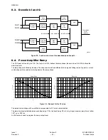
The baseband circuit utilises a two-chip GSM chipset developed by Texas Instruments. One chip (HERCULES) carries out
signal processing with DSP and CPU, and the second chip (OMEGA) contains the analogue interface and power control.
Figure 6.1: Baseband Block Diagram
6.2.
Keypad
The Keypad has a 5 x 5 matrix, allowing 25 keys to be scanned. When a key being pressed, a keypad interrupt is generated.
To find which key has been pressed, the software asserts each column in turn and reads which row is active. Because of key-
bounce, the key press is confirmed by reading the row again approximately 20ms later.
As the End Key doubles for the ON/OFF key, it is allocated an entire row of the keyboard scan.
The Keyboard scanning is software controlled, Key pressed is indicated by an interrupt, but key release is controlled by
software.
SPI
CPU
CORE
ROM
&
RAM
API
PLL &
CLOCKS
XIO
TEST &
EMULATION
LEAD Megamodule
TEST &
EMULATION
DMA
ARM
CORE
RIF
TPU
TDMA
TIME-
BASE
MEMORY
I/F
RTC
ARM I/O
SIM
I/F
BURST
STORE
10-Bit
I DAC
GMSK
MOD
10-Bit
Q DAC
LPF
LPF
ANTIALIASING
FILTER
DIFF
ENCODE
ANTIALIASING
FILTER
SIGMA-DELTA
SIGMA-DELTA
FILTER
FILTER
VOICEBAND
SERIAL I/F
BASEBAND SERIAL I/F
MCU
SERIAL I/F
ULPD
IRQ
KEYPAD
BACK-
LIGHT
SIM
CARD
MONITORING
10-BIT A/D
HERCULES-ROM2
OMEGA
SIM CARD
HOLDER
INTERNAL REGISTERS
SIGMA-DELTA
SIGMA-DELTA
BPF
BPF
LPF
SYSTEM
SIMULATOR
(DAI)
APC
(10-Bit D/A)
BATTERY
CHARGER I/F
AFC
(13-Bit D/A)
RF INTERFACE SIGNAL
TEST
HEADSET
JACK
VIBRATOR
LCD
ACCESSORY
CONNECTOR
TEST
MOBILE2
JTAG
BATTERY
TERMINALS
BATTERY
CLOCK
GEN.
DAI I/F
ULI
ULQ
DLI
DLQ
PARAMP
AFC
EXT_PWR
VBAT
BAT_ID
BAT_TEMP
13MHz
nINT1
RX_AUDIO
TX_AUDIO
KEY PCB CONNECTOR
RF INTERFACE
SIGNAL
D28V
D18V
nINT2
TSP
REGULATOR
PWR CONT.
SIM REG. &
SHIFTER
JTAG
MCSI
UART
UART
IrDA
INTH
INTH
WDT
CLKM
SLICER
uWIRE
I/F
SPI
TIMER2
TIMER1
TSP
UART
Modem
PWT
PWL
LPG
JTAG
SRAM
256k*8
FLASH
1M*16
MCP
uWIRE I/F
I/O
CTLR
LED
DRV.
DTHF
DRIVER
PHF
DRIVER
UART
I/F
PATH CTRL
SERIAL_DN
ACC. I/F
RF_EN
FET SW.
ACC. ASIC
SRAM
2M
FLASH
1M*16
nACC_SENSE
DATA_MODE1
RTC IC
U604
U601
U602
10338-1
32k Xtal
(See Table)
GD93
32M
FLASH
SRAM
4M + 2M + 2M
Содержание EB-GD93
Страница 4: ...Issue 1 Section MCUK001001G8 Revision 0 iv Technical Guide This page is left intentionally blank...
Страница 14: ...RF OVERVIEW Issue 1 Section 3 MCUK001001G8 Revision 0 10 Technical Guide This page is intentionally blank...
Страница 18: ...TRANSMITTER Issue 1 Section 4 MCUK001001G8 Revision 0 14 Technical Guide This page is intentionally blank...
Страница 22: ...RECEIVER Issue 1 Section 5 MCUK001001G8 Revision 0 18 Technical Guide This page is intentionally blank...
Страница 46: ...Printed in UK UK001001500PJ...


