


INTERFACES AND TEST POINTS
Issue 1
Section 2
MCUK991001G8
Revision 0
– 4 –
Technical Guide
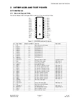
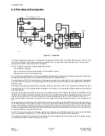
2.1.2 External Interface
The GD30 and GD50 telephones have two external connectors:
1.
a multi-way connector for use with external accessories such as hands free kits and PC data card.
2.
additional contacts for charging the battery pack while inserted in the desktop charger.
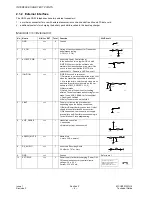
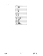
Main Unit <==> External I/O
No.
Name
H/H <=> EXT
Total
Function
H/H Circuit
1
GND
==>
6
Ground
2
PA_ON
==>
1
Gating of spectrum analyser for Transmitter
performance testing
L: Off, Hi - Z: On)
3
nLOGIC_PWR
==>
1
Accessory Power Control signal.
In the handsfree this is logical OR’ed with
IGNITION in order that the software can
maintain the Handsfree power-on state if the
user is in a call and that the IGNITION is
switched off. L: Power-on, Hi-Z: Power-off
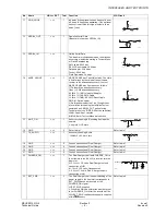
4
IGNITION
<==
1
IGNITION is used in two cases.
1) Determine the mode of operation of the H/H
when the Handsfree accessory is attached.
L: At a suitable time enter dummy sleep mode
and therefore minimise the drain on the car
battery (nLOGIC_POWER = Hi - Z)
H: Normal mode
2) Satisfy 2nd of 2 conditions for sending
initialise Testset command and entering Testset
mode. (see nADP_SENSE for 1st condition)
L: Condition 2 satisfied
H: Enter Testset mode not satisfied
5
VBAT
<=>
1
The pin is either an input or an output
depending upon the battery connection.
1) Battery/Dummy battery connected: Output
supply terminal for attached accessories.
2) No connection: Low current input supply
terminal for non-RF performance checking in
Testset Mode or Flash programming.
6
nH/F_SENSE
<==
1
Handsfree sense line
L: connected
H (internal pull-up): disconnected
7
nRADIO_MUTE
==>
1
Radio Mute
L: mute, Hi-Z: unmute)
8
RX_AUDIO
==>
1
Accessory Receiving Audio
-16 dBm0 = 76.7m Vrms
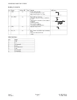
9
GND
==>
Ground
Refer to pin 1
10
EXT-PWR
<==
2
Power supply for battery charging, Power ON/
Off control and accessory control circuits.
Voltage: 5.8 ± 0.2 V
Current: 650 ± 50 mA
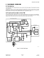
10095-1
10k
330p
10096-1
330
10097-1
330
50k
200k
10098-1
10099-1
330
100k
10100-1
330
50k
200k
10101-1
560
1 F
10102-1
10103-1
Trickle Charge Circuit
Power On/Off Control Circuit
Rapid Charge Circuit
Accessory Control Circuit
Содержание EB-GD30
Страница 4: ...Issue 1 Section MCUK991001G8 Revision 0 iv Technical Guide This page is left intentionally blank...
Страница 22: ...RECEIVER Issue 1 Section 5 MCUK991001G8 Revision 0 18 Technical Guide This page is left intentionally blank...
Страница 34: ...GEMINI Issue 1 Section 7 MCUK991001G8 Revision 0 30 Technical Guide This page is left intentionally blank...


