


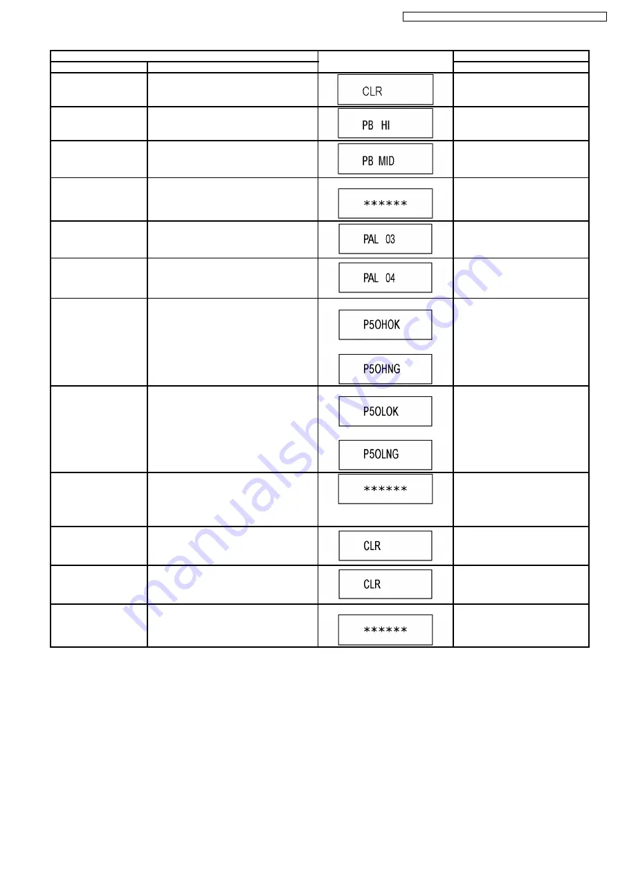
Item
FL display
Key operation
Mode name
Description
(Remote controller key)
Initialize Service
Last Drive Error, Error history and Error
Codes stored on the unit are initialized to
factory setting.
Press [9] [9] in service mode.
PB HIGH Signal Output
8 pin of AV 1 Jack (PB HIGH terminal) is High
(approx. 11V DC).
Press [5] [2] in service mode.
PB
MIDDLE
Signal
Output
8 pin of AV 1 Jack (PB HIGH terminal) is
Middle (approx. 5.5V DC)
Press [5] [3] in service mode.
Finishing service mode
Release Service Mode.
Display in STOP (E-E) mode.
Press power button on the front
panel or Remote controller in
service mode.
AV2(V)/AV1(Y/C)
I/O
Setting
Set input to AV2 (V) and set output to AV1
(Y/C) for I/O checking
Press [8] [2] in service mode.
AV2(RGB)/AV1(V)
I/OSetting
Set input to AV2 (RGB) and set output to AV1
(V) for I/O checking
Press [8] [3] in service mode.
P50(H) Output
Timer Microprocessor IC7504-76 output High
signal for AV1-pin 10 passing through inverter
(approx. 0V DC at AV1-pin 10).
When OK.
When NG.
Press [8] [4] in service mode.
P50(L) Output
Timer Microprocessor IC7504-76 output Low
signal for AV1-pin 10 passing through inverter
(approx. 4.4V DC at AV1-pin 10).
When OK.
When NG.
Press [8] [5] in service mode.
Tray OPEN/CLOSE Test The RAM drive tray is opened and closed
repeatedly.
“*” is number of open/close cycle
times.
Press [9] [1] in service mode*When
releasing this mode, press the
[POWER]
button
of
Remote
Controller more than 10 seconds.
Error code initialization
Initialization of the last error code held by
timer (Write in F00)
Press [9] [8] in service mode.
Initialize Service
Last Drive Error, Error history and Error
Codes stored on the unit are initialized to
factory setting.
Press [9] [9] in service mode.
Finishing service mode
Release Service Mode.
Display in STOP (E-E) mode.
Press power button on the front
panel or Remote controller in
service mode.
45
DMR-ES35VGN / DMR-ES35VGC / DMR-ES35VGCS / DMR-ES35VEE
Содержание DMR-ES35VGN
Страница 4: ...1 2 Caution for AC Mains Lead For GC only 4 DMR ES35VGN DMR ES35VGC DMR ES35VGCS DMR ES35VEE ...
Страница 7: ...3 Precaution of Laser Diode 7 DMR ES35VGN DMR ES35VGC DMR ES35VGCS DMR ES35VEE ...
Страница 10: ...6 Specifications For GN GC GCS 10 DMR ES35VGN DMR ES35VGC DMR ES35VGCS DMR ES35VEE ...
Страница 11: ...11 DMR ES35VGN DMR ES35VGC DMR ES35VGCS DMR ES35VEE ...
Страница 12: ... For EE 12 DMR ES35VGN DMR ES35VGC DMR ES35VGCS DMR ES35VEE ...
Страница 13: ...13 DMR ES35VGN DMR ES35VGC DMR ES35VGCS DMR ES35VEE ...
Страница 15: ...Audio Video cable 15 DMR ES35VGN DMR ES35VGC DMR ES35VGCS DMR ES35VEE ...
Страница 17: ...8 2 Remote Control Operation For EE 17 DMR ES35VGN DMR ES35VGC DMR ES35VGCS DMR ES35VEE ...
Страница 18: ...8 3 Main Unit Operation 18 DMR ES35VGN DMR ES35VGC DMR ES35VGCS DMR ES35VEE ...
Страница 19: ...8 4 Main Unit Panel Display 19 DMR ES35VGN DMR ES35VGC DMR ES35VGCS DMR ES35VEE ...
Страница 20: ...8 5 Disc Information 8 5 1 Discs for recording play 20 DMR ES35VGN DMR ES35VGC DMR ES35VGCS DMR ES35VEE ...
Страница 21: ...8 5 2 Discs for playing 21 DMR ES35VGN DMR ES35VGC DMR ES35VGCS DMR ES35VEE ...
Страница 22: ...22 DMR ES35VGN DMR ES35VGC DMR ES35VGCS DMR ES35VEE ...
Страница 23: ...23 DMR ES35VGN DMR ES35VGC DMR ES35VGCS DMR ES35VEE ...
Страница 24: ...8 5 3 Data playable format DivX MP3 JPEG TIFF 24 DMR ES35VGN DMR ES35VGC DMR ES35VGCS DMR ES35VEE ...
Страница 25: ...8 6 ABOUT DivX 25 DMR ES35VGN DMR ES35VGC DMR ES35VGCS DMR ES35VEE ...
Страница 26: ...26 DMR ES35VGN DMR ES35VGC DMR ES35VGCS DMR ES35VEE ...
Страница 27: ...27 DMR ES35VGN DMR ES35VGC DMR ES35VGCS DMR ES35VEE ...
Страница 28: ...28 DMR ES35VGN DMR ES35VGC DMR ES35VGCS DMR ES35VEE ...
Страница 29: ...29 DMR ES35VGN DMR ES35VGC DMR ES35VGCS DMR ES35VEE ...
Страница 30: ...30 DMR ES35VGN DMR ES35VGC DMR ES35VGCS DMR ES35VEE ...
Страница 32: ...8 7 2 Connection to amplifier system component 32 DMR ES35VGN DMR ES35VGC DMR ES35VGCS DMR ES35VEE ...
Страница 34: ...8 8 2 Connection to amplifier system component 34 DMR ES35VGN DMR ES35VGC DMR ES35VGCS DMR ES35VEE ...
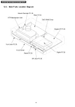
Страница 52: ...12 3 Main Parts Location Diagram 52 DMR ES35VGN DMR ES35VGC DMR ES35VGCS DMR ES35VEE ...
Страница 63: ...13 1 3 Checking and Repairing of Main P C B 63 DMR ES35VGN DMR ES35VGC DMR ES35VGCS DMR ES35VEE ...
Страница 65: ...13 2 2 Notice for Replacing Capstan Motor 65 DMR ES35VGN DMR ES35VGC DMR ES35VGCS DMR ES35VEE ...
Страница 66: ...13 2 3 Items that should be done after replacing parts 66 DMR ES35VGN DMR ES35VGC DMR ES35VGCS DMR ES35VEE ...
Страница 67: ...67 DMR ES35VGN DMR ES35VGC DMR ES35VGCS DMR ES35VEE ...
Страница 68: ...68 DMR ES35VGN DMR ES35VGC DMR ES35VGCS DMR ES35VEE ...
Страница 86: ...DMR ES35VGN DMR ES35VGC DMR ES35VGCS DMR ES35VEE 86 ...
Страница 94: ...DMR ES35VGN DMR ES35VGC DMR ES35VGCS DMR ES35VEE 94 ...
Страница 96: ...96 DMR ES35VGN DMR ES35VGC DMR ES35VGCS DMR ES35VEE ...
Страница 126: ...DMR ES35VGN DMR ES35VGC DMR ES35VGCS DMR ES35VEE 126 ...
Страница 127: ...21 Exploded Views 21 1 Casing Parts Mechanism Section1 127 DMR ES35VGN DMR ES35VGC DMR ES35VGCS DMR ES35VEE ...
Страница 128: ...21 2 Casing Parts Mechanism Section 2 128 DMR ES35VGN DMR ES35VGC DMR ES35VGCS DMR ES35VEE ...
Страница 129: ...21 3 VHS Mechanism Section 129 DMR ES35VGN DMR ES35VGC DMR ES35VGCS DMR ES35VEE ...
Страница 130: ...21 4 Packing 130 DMR ES35VGN DMR ES35VGC DMR ES35VGCS DMR ES35VEE ...


