


23
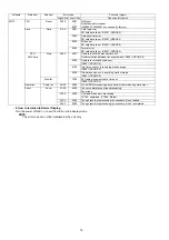
8.3.
Disassembly Procedure
8.3.1.
Removal of the Rear Case Unit
Fig. D1
No.
Item
Fig
Removal
1
Rear Case Unit
Card
Battery
3 Screws (A)
1 Screw (B)
FP9003(Flex)
FP9004(Flex)
Rear Case Unit
2
LCD Unit
LCD Unit
3
Top Operation Unit
1 Screw (C)
1 Screw (D)
FP9006(Flex)
Capton Tape
Top Operation Unit
4
Front Case Unit
FP9002(Flex)
2 Screws (E)
1 Screw (F)
3 Screws (G)
Front Case Unit
5
Main PCB
2 Screws (H)
Jack Door unit
FP9001(Flex)
FP9006(Flex)
P9001(Connector)
1 Locking tab
Main PCB
6
Lens Unit
1 Locking tab
Lens Unit
7
Battery Case
1 Screw (I)
3 Locking tabs
Strap Holder
Battery Case
8
Top Operation PCB
4 Screws (J)
Top Operation PCB
9
Flash Unit
1 Screw (K)
1 Locking tab
Nut Plate
Flash Unit
10
Flash PCB
P8001(Connector)
P8002(Connector)
2 Locking tabs
Flash PCB
11
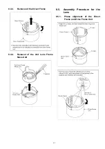
Lens Ornament Unit
3 Screws (L)
Lens Ornament Unit
12
AF-MF Aspect FPC
2 Screws (M)
AS Click Spring
AF Click Spring
2 Focus Knobs
2 Focus Sheets
1 Screw (N)
Lens Frame
2 Screws (O)
AF-MF Aspect FPC
Содержание DMCLX1PP - DIGITAL STILL CAMERA
Страница 8: ...8 NOTE Above caution is applicable for a battery pack which is for DMC LX1 series as well ...
Страница 12: ...12 4 Specifications ...
Страница 13: ...13 5 Location of Controls and Components ...
Страница 14: ...14 ...
Страница 15: ...15 ...
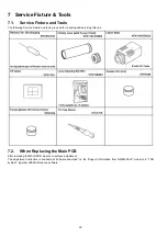
Страница 22: ...22 8 Disassembly and Assembly Instructions 8 1 Disassembly Flow Chart 8 2 PCB Location ...
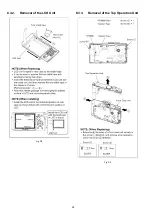
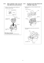
Страница 24: ...24 8 3 2 Removal of the LCD Unit Fig D2 8 3 3 Removal of the Top Operation Unit Fig D3 ...
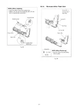
Страница 26: ...26 8 3 7 Removal of the Battery Case Fig D7 8 3 8 Removal of the Top Operation PCB Fig D8 ...
Страница 27: ...27 Fig D9 8 3 9 Removal of the Flash Unit Fig D10 ...
Страница 36: ......
Страница 52: ...S 16 ...