Panasonic CS-SA12CKP Скачать руководство пользователя страница 37

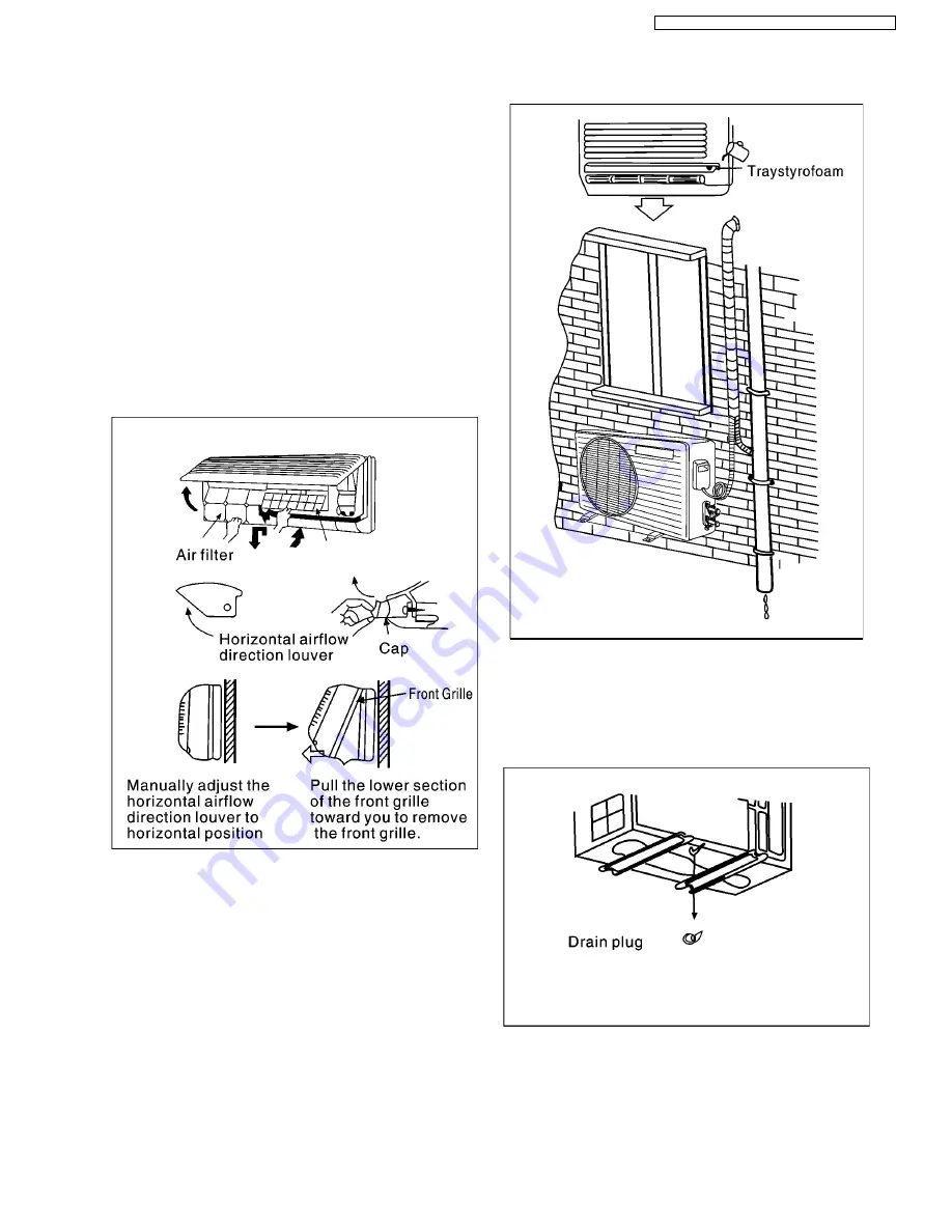
8.8.1. Checking the drainage

 1. Remove the front grille from the cabinet

When removing the front grille for maintenance purposes,
etc, carry out by the following procedures.
 a. Set the vertical airflow direction louver (1) to the

horizontal position.

 b. Remove the two caps on the front grille as shown in the

illustration at right, and then remove the two mounting
screws.

 c. Pull the lower section of the front grille toward you to

remove the front grille.

When reinstalling the front grille, first set the vertical airflow
direction louver to the horizontal position, and then carry out
by steps 3 and 2 in that order. At this time check to sure that
the fixing tabs on the top inside edge of the front grille are
securely inserted into the respective slots.

 2. Checking the drainage

     • 

• 

• 

• 

Pout a glass of water into the drain train traystyroform.

     • 

• 

• 

• 

Ensure water flow out from drain hose of indoor unit.

 3. Drainage control for outdoor unit

     • 

• 

• 

• 

If a drainage plug is applied, the outdoor unit should at
least be 3 centimeters high from the floor.

     • 

• 

• 

• 

If is better not to use the drainage plug if the
temperature is lower than 0°C, since icing of the
condensed water may block the water flow.

8.8. Checking the drainage and connecting the cable to indoor unit

37

CS-SA9CKP CU-SA9CKP5 / CS-SA12CKP CU-SA12CKP5

Содержание CS-SA12CKP

Страница 1: ...nditioner Co Ltd GMAC All rights reserved Unauthorized copying and distribution is a violation of law CS SA9CKP CU SA9CKP5 CS SA12CKP CU SA12CKP5 10 Disassembly of the parts 47 11 Trouble shooting guide 51 12 Technical Data 53 13 Exploded View 56 14 Replacement Parts List 57 15 Exploded View 58 16 Replacement Parts List 59 17 ELECTRONIC CIRCUIT DIAGRAM 60 Room Air Conditioners CONTENTS Page Page O...

Страница 2: ...eed Medium Speed Low Speed Automatic Speed Airflow Direction Control Auto Airflow Direction Airflow Direction Manual Control Room Temperature Setting Temperature Setting 16 C to 30 C Auto Operation Timer Operation Selection Stop Start Operation Control set the ON OFF Timer hourly later Set Cancel Timer Operation Set timer Cancel the set timer 2 CS SA9CKP CU SA9CKP5 CS SA12CKP CU SA12CKP5 ...

Страница 3: ...ator is between 30 C and 40 C indoor fan will run at Super Low or Low speed When temperature of evaporator reaches 34 C Warm Booting Operation ends High Med Low Auto Auto Fan Speed Automatic Airflow Direction Control The louver automatically swings up and down Airflow Direction Manual Control Auto Mode Operation Selection Button Power Switch ON OFF Signal Receiving Sound Control Test Run Operation...

Страница 4: ...ture of evaporator reaches 51 C outdoor fan stops and will restart when the temperature of evaporator declines to 49 C When the temperature of evaporator reaches 65 C compressor will stop If the outdoor fan does not run after the compressor is activated for 50sec the compressor will stop only in cooling and soft dry mode oteration If the unit is stopped during Heating Operation the 4 way valve wil...

Страница 5: ...ing High38 Low29 Heating High48 Electrical Data Input W Cooling 940 985 Heating 800 830 Running Current A Cooling 4 40 4 34 Heating 3 75 3 70 EER W W Cooling 2 87 2 79 COP Heating 3 88 3 80 Starting Current A 21 Piping Connection Port Flare piping Inch Inch G half union 3 8 L half union 1 4 G 3 way valve 3 8 L 2 way valve 1 4 Piping Size Flare piping Inch Inch G gad side 3 8 L liquid side 1 4 G ga...

Страница 6: ...PI 18 19 Dimensions mm 610 315 25 4 706 2 482 6 22 Refrigerant Control Device Capillary Tube Refrigeration Oil c c SUNISO 4GDID or ATMOS M60 350 Refrigerant R 22 g 840 Thermostat Electronic Control Protection Device Overload Protector Capillary Length mm Cooling 470 Heating 1160 Circulation L min Cooling 13 4 Heating 4 5 Inner dia mm Cooling 1 5 Heating 1 2 Air Filter P P Honeycomb Refrigerant Cir...

Страница 7: ...230 1250 Heating 1100 1130 Running Current A Cooling 5 75 5 60 Heating 5 15 5 05 EER W W Cooling 2 72 2 72 COP Heating 3 64 3 58 Starting Current A 26 Piping Connection Port Flare piping Inch Inch G half union 1 2 L half union 1 4 G 3 way valve 1 2 L 2 way valve 1 4 Piping Size Flare piping Inch Inch G gad side 1 2 L liquid side 1 4 G gas side 1 2 L liquid side 1 4 Drain Hose Inner diameter mm 12 ...

Страница 8: ...igerant Control Device Capillary Tube Refrigeration Oil c c SUNISO 4GDID or ATMOS M60 350 Refrigerant R 22 g 940 Thermostat Electronic Control Protection Device Overload Protector Capillary Length mm Cooling 470 Heating 1160 Circulation L min Cooling 13 4 Heating 4 5 Inner dia mm Cooling 1 5 Heating 1 2 Air Filter P P Honeycomb Refrigerant Circulation Control Device Capillary Compressor Capacitor ...

Страница 9: ...3 Dimensions 9 CS SA9CKP CU SA9CKP5 CS SA12CKP CU SA12CKP5 ...

Страница 10: ...10 CS SA9CKP CU SA9CKP5 CS SA12CKP CU SA12CKP5 ...

Страница 11: ...4 Refrigeration Cycle Diagram 11 CS SA9CKP CU SA9CKP5 CS SA12CKP CU SA12CKP5 ...

Страница 12: ...5 Block Diagram 12 CS SA9CKP CU SA9CKP5 CS SA12CKP CU SA12CKP5 ...

Страница 13: ...6 Wiring Diagram 13 CS SA9CKP CU SA9CKP5 CS SA12CKP CU SA12CKP5 ...

Страница 14: ...s to balance the pressure in the refrigeration cycle Protection of compressor 7 min The unit will automatically operate in 7 minutes even if the room temperature is not reached Prevention of raising the humidity If the outdoor fan motor does not run 50 seconds after the compressor starts the compressor will cease and restart in 3 minutes Time Delay Safety Control is effective If this symptom occur...

Страница 15: ...or cooling Operation During Cooling Mode Operation use remote controller to select Automatic Fan Speed Fan speed will be at the point between high speed and medium speed Deodorization control 15 CS SA9CKP CU SA9CKP5 CS SA12CKP CU SA12CKP5 ...

Страница 16: ...eed Once soft Dry mode operation is turned off indoor fan compressor and outdoor fan will stop for 6 minutes During cooling mode operation if the compressor ceased it will not restart within 3 minutes Same as the denotation in Cooling Operation P 14 During Soft Dry Mode Operation compressor will stop for at least 6 min Same as the denotation in Cooling Operation P 14 Same as the denotation in Cool...

Страница 17: ...Time Graph for soft dry operation 17 CS SA9CKP CU SA9CKP5 CS SA12CKP CU SA12CKP5 ...

Страница 18: ...emote controller compressor stops and will not restart within 4 minutes 3 minutes after the compressor stopped indoor fan will stop for 1 minute Then indoor fan will resume operation with the speed at super low When temperature of indoor heat exchanger rises to 51 C outdoor fan will stop when temperature of indoor heat exchanger falls to 49 C outdoor fan will restart When temperature of indoor hea...

Страница 19: ...eration When selecting automatic fan mode by remote controller during heating mode operation the fan will operate at different speed under different conditiors according to the temperature of indoor heat exchanger 19 CS SA9CKP CU SA9CKP5 CS SA12CKP CU SA12CKP5 ...

Страница 20: ...ring heating operation if the accumulative stopping time of outdoor fan reaches 60 minutes deicing operation will start 1 minute after compressor starts Deicing operation ends under conditions below 1 After 12 minutes 2 Temperature of outdoor unit rises to 4 C 3 Because of time delay Td deicing operation will not end immediately Once deicing starts it will not end within 60 seconds When deicing op...

Страница 21: ...Time Graph for Normal Deicing Operation Time Graph for Overload Deicing 21 CS SA9CKP CU SA9CKP5 CS SA12CKP CU SA12CKP5 ...

Страница 22: ...ll immediately operate 4 After the operation mode has been determined the mode does not change However Soft Dry mode operation induces cooling mode operation 5 If automatic mode operation is started while the unit is operating operation will continue If current operation is in cooling mode including the cooling mode operation when is a part of Soft Dry mode operation it will be maintained and if c...

Страница 23: ...n speed set the available range for fan speed is from H to SLo Manual Fan Speed Control Basic fan speed can be manually adjusted Lo Med Hi by using the fan speed selection button Basic Fan Speed Rotating Speed Of Indoor Fan Motor 23 CS SA9CKP CU SA9CKP5 CS SA12CKP CU SA12CKP5 ...

Страница 24: ...he remote controller is used to stop the operation the discharge vent is closed with airflow direction louver Notes In heating mode operation 1 Airflow direction automatic control The airflow direction is automatically adjusted to horizontal direction when the temperature of indoor heat exchanger is low and it will be automatically adjusted downward while the indoor temperature rises 2 Airflow dir...

Страница 25: ...ir circulation A place where air circulation in the room is good A place where drainage can be easily done A place where noise prevention is taken into consideration Do not install the unit near the door way Ensure the spaces indicated by arrows from the wall ceiling fence or other obstacles Recommended installation height for indoor unit shall be at least 2 3m If an awning is built over the unit ...

Страница 26: ...26 CS SA9CKP CU SA9CKP5 CS SA12CKP CU SA12CKP5 ...

Страница 27: ...ide piping Insulated drain hose 42N m Gas side piping Insulation materials 55N m Gas side piping Spanner Half union 4 Connecting piping and cable to the outdoor unit Additional drain hose Specified torque wrenches Outer diameter 1 55mm 18N m Liquid side 1 Connecting the piping to the outdoor unit P 35 Connecting cable 42N m Gas side 5 core wire 1 5mm2 55N m Gas side 2 Connecting the cable P 35 Loc...

Страница 28: ...ld be more than eye level 8 3 1 2 Outdoor unit If an awning is built over the unit to prevent direct sunlight or rain exposure be careful that heat radiation from the condenser is not restricted There should not be ary animals or plants which could be affected by hot air discharged Ensure the spaces indicated by arrows from the wall ceiling fence or other obstacles 8 3 1 3 Piping lenght and elevat...

Страница 29: ... hole core drill Line according to the arrows marked on the lower left and right side of the installation plate To drill a hole in the wall and install a sleeve for tube assiy Drill a Ø70mm hole sloping downward toward the outside of the wall Insert the sleeve for tube assiy through the hole Fix the bushing to the sleeve Extrude 15mm of the sleeve then cut Caution When the wall is horrow please be...

Страница 30: ...urrs from cut edges of pipes Turn the pipe end down to avoid the metal powder entering the pipe Caution If burrs are not removed the may cause a gas leakage 8 4 1 3 Flaring the pipe Insert the flare nuts mounted on the connection ports of both indoor and outdoor unit onto the copper pipes Fit the copper pipe end into the bar of flare tool about 0 5 1 5mm higher see Fig A Flare the pipe ends Fig A ...

Страница 31: ...ear top of the indoor unit with the upper edge of the installation plate Ensure the hooks are properly seated on the installation plate by moving it left and right 6 Connecting the piping to the indoor unit Align the center of the piping and sufficiently tighten the flare nut with fingers Finally tighten the flare nut with torgue wrench until the wrench clicks When tightening the flare nut with to...

Страница 32: ...e to the hole Pull out the drain hose Exchange the hose and cap 2 Insert the piping and connecting cable to indoor side through the hole 3 Insert the connecting cable into the connecting cable Do not connect the cable to the indoor unit Make a small loop with the cable for easy con nection 32 CS SA9CKP CU SA9CKP5 CS SA12CKP CU SA12CKP5 ...

Страница 33: ...tighten the flare nut with fingers Finally tighten the flare nut with torque wrench until the wrench clicks When tightening the flare nut with torque wrench ensure the direction for tightening follows arrow on the wrench Model Piping side Torque CS SA9CKP CU SACKP5 Liquid side 1 4 18N m CS SA12CKP5 CU SA12CKP5 CS SA9CKP CU SACKP5 Gas side 3 8 42N m CS SA12CKP5 CU SA12CKP5 Gas side 1 2 55N m 6 Set ...

Страница 34: ...he way to the left on the installation plate Refer to the section cut and flaring the piping in the directions for the outdoor unit see P 30 8 5 5 Pull the connecting cable into the indoor unit 8 5 6 Connecting the piping Refer to the section connecting the piping in the directions for the indoor unit Connecting the piping to the outdoor unit and checking the gas leakage 8 5 7 Connecting the cable...

Страница 35: ...s side 3 8 42N m CS SA12CKP CU SA12CKP5 Gas side 1 2 55N m Caution When connecting the piping always use a torque wrench Other tools may cause damage to the flare nut because of improper force 3 Ensure not to let the piping exposed to air 8 6 2 Connecting the cable 1 Remove the top cover from the unit by loosening the four screws 2 Remove the control board cover by loosening the screw 3 Connect th...

Страница 36: ... way valves 2 Remove the service port cap from the 3 way valve 3 To open the valve turn the valve stem of 2 way valve counter clockwise approximately 90 and hold it there for 10 seconds then close it 4 Check a gas leakage of the connecting portion of the piping 5 Set the both 2 way and 3 way valves to open position with the hexagonal wrench for the unit operation 36 CS SA9CKP CU SA9CKP5 CS SA12CKP...

Страница 37: ...he horizontal position and then carry out by steps 3 and 2 in that order At this time check to sure that the fixing tabs on the top inside edge of the front grille are securely inserted into the respective slots 2 Checking the drainage Pout a glass of water into the drain train traystyroform Ensure water flow out from drain hose of indoor unit 3 Drainage control for outdoor unit If a drainage plug...

Страница 38: ...able to the terminals of the indoor unit 8 8 3 Connect the cable to the indoor unit Connect the locally approved cable 1 5mm2 to the terminals on the control board individually according to the outdoor connection Ensure the colour of wires of outdoor unit and the terminal No are the same to the indoors respectively Secure the cable onto the board with the holder clamper Both the unit and the power...

Страница 39: ...e correct Be sure that both batteries are new Re attach the cover Slide the cover back into position 3 Operate the unit at cooling mode operation for 15 minutes or more 8 9 2 Evaluation of the performance 1 Operate the air conditioner for 15 minutes 2 Measure the temperature of the intake and discharge air 3 Ensure the difference betwan the intake temperature and the discharge is more than 8 C in ...

Страница 40: ...ockwise Push pin Operation Open Open Closed Counter clockwise With valve cap With cap Pumping down Closed Open Open transfering clockwise counter clockwise Connected manifold gauge Evacuation Open Open Open Servicing With vacuum pump Charging Open Open Open servicing With charging cylinder Pressure check Open Servicing Open Open Connected manifold gauge Gas releasing Open Servicing Open Open Conne...

Страница 41: ...rvice port cap to a torque of 1 8kg m 18N m 6 Set the 3 way valve to the opened position The air in the indoor unit and in the piping must be purged If air remains in the refrigeration pipings it will affect the compressor reduce the cooling capacity and could lead to a malfunction 7 Mount the valve s stem nuts to the 3 way and 3 way valve 8 Check for gas leakage At this time especially check for ...

Страница 42: ... the charge hose 5 Set the 2 way valve to the close position 6 Operate the air conditioner at the cooling cycle and stop it when the gauge indicates 2 kg cm2 G 0 1Mpa If the unit cannot be operate at the cooling mode operation weather is rather cool press the pump down switch on the indoor unit so that the unit can be operated 7 Immediately set 3 way valve to the closed position Do this quick so t...

Страница 43: ... flare nut on the 2 way valve 4 Check for gas leakage Check the flare connections for gas leakage 5 Discharge the refrigerant Open the valve on the charging cylinder and discharge the refrigerant unit the gauge indicates 3 to 5 kg cm2 G 0 3 to 0 5 Mpa 6 Disconnect the charge set and the charging cylinder and set the 2 way and 3 way valves to the open position Be sure to use a hexagonal wrench to o...

Страница 44: ...e on the charge set and discharge the refrigerant until the gauge indicates 0 5 1 kg cm2 G 0 05 0 1Mpa If there is no air in the refrigerant cycle the pressure when the air conditioner is not running is higher than 1kg cm2 G 0 1Mpa discharge the refrigerant until the gauge indicates 0 5 to 1 kg cm2 G 0 05 to 0 1Mpa If this is the case it will not be necessary to apply a evacuation Discharge the re...

Страница 45: ...e has moved toward 76cmHg 0 1Mpa vacuum of 4 mmHg or less 3 Close the valve low side on the charge set turn off the vacuum pump and confirm that the gauge needle dose not move approximately 5 minutes after turning off the vacuum pump 4 Disconnect the charge hose from the vacuum Vacuum oil If the vacuum pump oil becomes dirty or depleted replenish as needed 45 CS SA9CKP CU SA9CKP5 CS SA12CKP CU SA1...

Страница 46: ...y 150g each time while operating the air conditioner in the cooling cycle However one time is not sufficient wait approximately 1 minute and then repeat the procedure Pumping down pin This is different from previous procedures Because you are charging with liquid refrigerant from the gas side absolutely do not attempt to charge with large amounts of liquid refrigerant while operating the air condi...

Страница 47: ...he fan motor 1 Remove the connector CN MTR of fan motor and connector CN STM of step fan motor loosen the grounding wire yellow green and pull the sensor out from the socket See Fig 1 2 Remove the control board Loosen the upper left and right tabs and pull out the control board Refer to Fig 2 Fig 3 Fig 4 Fig 1 Fig 2 Fig 3 Fig 4 10 Disassembly of the parts 47 CS SA9CKP CU SA9CKP5 CS SA12CKP CU SA12...

Страница 48: ...n motor Loosen the fan motor securing screw at the junction of the cross fan see Fig 5 Remove the special tab and pull the fan motor out see Fig 6 Fig 7 Fig 5 Fig 6 Fig 7 48 CS SA9CKP CU SA9CKP5 CS SA12CKP CU SA12CKP5 ...

Страница 49: ...w of the front grille pull the front grille down towards you 2 Loosen the bearing on the left side of the cross flow fan 3 Take off the securing tabs to the left of the heat exchanger Pull the heat exchanger forward left side Fig 10 The cross flow fan can be removed Fig 10 Fig 8 Fig 9 Fig 10 49 CS SA9CKP CU SA9CKP5 CS SA12CKP CU SA12CKP5 ...

Страница 50: ... button to reset the remote control to the original set by manufacturer Fig 11 Fig 11 Fig 12 Remove the back lid of the remote controller and you will find terminal two s it is possible to select from 2 types of transmission codes by shorting the terminals 50 CS SA9CKP CU SA9CKP5 CS SA12CKP CU SA12CKP5 ...

Страница 51: ... Such problems include insufficient insulation problem with the power source malfunction of compressor or fan The normal outlet air temperature and pressure of the refrigeration cycle depends on various conditions the standard values for them are shown in the table to the right 11 Trouble shooting guide 51 CS SA9CKP CU SA9CKP5 CS SA12CKP CU SA12CKP5 ...

Страница 52: ...uring operation becomes approximately 80 lower than the normal level Insufficient compressing of a compressor The discharge tube of the compressor becomes abnormally hot normally 70 90 C The difference between high pressure and low pressure becomes almost zero Electric current reaches a high level abnormally and the value exceeds the limit of an ammeter In some cases a breaker turns off Locked com...

Страница 53: ...12 Technical Data Thermostat characteristics CS SA9CKP CU SA12CKP5 53 CS SA9CKP CU SA9CKP5 CS SA12CKP CU SA12CKP5 ...

Страница 54: ... Operating characteristics CS SA9CKP CU SA9CKP5 CS SA12CKP CU SA12CKP5 54 CS SA9CKP CU SA9CKP5 CS SA12CKP CU SA12CKP5 ...

Страница 55: ...13 Exploded View CS SA9CKP CS SA12CKP 55 CS SA9CKP CU SA9CKP5 CS SA12CKP CU SA12CKP5 ...

Страница 56: ... 1 CWA401030 CWA401030 20 SENSOR COMPLETE 1 CWA50C2064 CWA50C2064 21 CONTROL PCB 1 CWA742817 CWA742818 22 RECEIVER 1 CWA742509 CWA742509 23 COVER CONTROL BOX 1 CWH131103 CWH131103 24 INDICATOR COMPLETE 1 CWE39C1048 CWE39C1048 25 HOLDER INDICATOR 1 CWD932170 CWD932170 26 INDICATOR PCB 1 CWA742707 CWA742707 27 LEAD WIRE INDICATOR 1 CWA67C4037 CWA67C4037 28 FRONT COVER CONTROL BOX 1 CWH131102 CWH1311...

Страница 57: ...15 Exploded View CU SA9CKP5 CU SA12CKP5 57 CS SA9CKP CU SA9CKP5 CS SA12CKP CU SA12CKP5 ...

Страница 58: ...2435 18 V COIL COMPLETE 1 CWA43C2001 CWA43C2001 19 STRAI NER 1 CWB11025 CWB11025 20 SOUND PROOF PANEL 1 CWH15268 CWH151026 21 SOUND PROOF MATERIAL 1 CWG30779 CWG30779 22 OVER LOAD PROTECTOR 1 CWA12371 23 HOLDER O L P 1 CWH7041200 24 TERMINAL COVER 1 CWH17006 CWH17006 25 NUT FOR TERMINAL COVER 1 CW7080300 CW7080300 26 CONTOL BOX COMPLETE 1 CWH14C3174 CWH14C3174 27 CONTROL BOARD 1 CWH102026 CWH10202...

Страница 59: ...1K BZ IC 14 3 RY C C16 35V 470 Q1 2SC1741A R30 10K R29 2 2K SSR1 RY M RY H 16 1 2 15 UN421F Q3 L2 A43036 R21 10K 12V 5V 78M05 AN78M12 12V C5 25V 470 C2 100 10V IC2 IC4 B A C D E F G 1 2 3 4 5 AC220 50Hz R22 10K D3 MA723TA D1 MA165TA C21 33 C11 0 01 ZNR3 454C367 RY HOT SSR2 CR4 A59015 CT1 A40322 AC AC 99 C AC HOT FM 1 L 2 N 3 4 TRS 3 2 6 7 8 3 2 6 7 8 GR BR BL W R BLUE BL BR W 4 WAY VALVE CAPACITOR...

Страница 60: ... 01 PH302C 330 330 330 KR 4 PH4 C23 10V 100 LED CS CU SA9BKP5 CS CU SA12BKP5 R24 53 6K 31 6K CS SA9BKP5 CS SA12BKP5 fig 2 I C 1 I C 1 p i n p i n 5 6 5 7 4 3 2 1 0 10 20 30 40 50 60 70 V 0 10 20 30 40 50 10 C C k 70 60 50 40 30 20 10 0 fig 1 S E N S O R T H E R M O R I S I S T O R C H A R A T E R I S T I C S 1 2 1 2 6 7 8 9 10 4 4 CN DISP CN DISP CN STM 5 4 3 2 1 2 5 TIMER O AIR SWING PIPE SENSOR ...

Страница 61: ...17 1 REMOTE CONTROL 61 CS SA9CKP CU SA9CKP5 CS SA12CKP CU SA12CKP5 ...

Страница 62: ...17 2 PRINTED CIRCUIT BOARD REMOTE CONTROL 62 CS SA9CKP CU SA9CKP5 CS SA12CKP CU SA12CKP5 Printed in China ...

Отзывы: