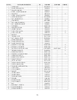
Panasonic CS-NE9NKE Скачать руководство пользователя страница 111

111 

REF. 

NO. 

PART NAME & DESCRIPTION 

QTY 

CS-WE9NKE 

CS-WE12NKE 

REMARK

1 CHASSY 

COMPLETE 

CWD50C1731 


2 FAN 

MOTOR 

ARW7666ACCB 

 O 

CROSS-FLOW FAN COMPLETE 

CWH02C1135 


4 BEARING 

ASS'Y 

CWH64K1010 


5 GENERATOR 

COMPLETE 

CWH94C0048 


6 EVAPORATOR 

COMPLETE 

CWB30C3968 

CWB30C3966 


FLARE NUT (LIQUID) 

CWT251030 


FLARE NUT (GAS) 

CWT251031 


9 HOLDER 

SENSOR 

CWH32143 


9a HOLDER 

SENSOR 

CWH321085 


10 BACK 

COVER 

CHASSIS 

CWD933463A 


11 

DISCHARGE GRILLE COMPLETE 

CWE20C3308 


12 VERTICAL 

VANE 

CWE241389 


13 VERTICAL 

VANE 

CWE241409 


14 CONNECTING 

BAR 

CWE261272 


18 FULCRUM 

CWH621139 


19 

HORIZONTAL VANE COMPLETE 

CWE24C1431 


20 

HORIZONTAL VANE COMPLETE 

CWE24C1421 


21 

AIR SWING MOTOR 

CWA981241 

 O 

22 

AIR SWING MOTOR 

CWA981299 

 O 

23 

CAP - DRAIN TRAY 

CWH521259 


24 SENSOR 

COMPLETE 

CWA50C2663 


25 

ELECTRONIC CONTROLLER - MAIN 

CWA73C6848 

CWA73C6849 

26 

ELECTRONIC CONTROLLER - HVU 

N0GE1F000002 

 O 

27 

CONTROL BOARD CASING 

CWH102456 


28 

CONTROL BOARD TOP COVER 

CWH131531 


29 

CONTROL BOARD FRONT COVER CO. 

CWH13C1286 


30 

TERMINAL BOARD COMPLETE 

CWA28C2364 


31 INDICATOR 

COMPLETE 

CWE39C1231 


32 INDICATOR 

HOLDER 

CWD933466 


33 

FRONT GRILLE COMPLETE 

CWE11C5435 

 O 

34 

GRILLE DOOR COMPLETE 

CWE14C1102 


35 

INTAKE GRILLE COMPLETE 

CWE22K1611 

 O 

36 

DECORATION BASE ASS'Y (L) 

CWE35K1145 


37 

DECORATION BASE ASS'Y (R) 

CWE35C1192 


38 

SCREW - FRONT GRILLE 

XTT4+16CFJ 


39 AIR 

FILTER 

CWD001326 


40 FLEXIBLE 

PIPE 

CWH851173 


41 REMOTE 

CONTROL 

COMPLETE 

CWA75C4153 

 O 

42 INSTALLATION 

PLATE 

CWH361134 


43 

BAG COMPLETE - INSTALLATION SCREW 

CWH82C1705 


44 OPERATING 

INSTRUCTION 

CWF568749 


45 INSTALLATION 

INSTRUCTION 

CWF615521 


46 INSTALLATION 

INSTRUCTION 

CWF615522 


47 INSTALLATION 

INSTRUCTION 

CWF615523 


48 INSTALLATION 

INSTRUCTION 

CWF615524 


49 INSTALLATION 

INSTRUCTION 

CWF615525 


50 BAG 

CWG861515 


Содержание CS-NE9NKE

Страница 1: ...2 Outdoor Unit 23 11 Installation Instruction 24 11 1 Select The Best Location 24 11 2 Indoor Unit 25 11 3 Outdoor Unit 30 12 Operation and Control 33 12 1 Basic Function 33 12 2 Indoor Fan Motor Ope...

Страница 2: ...n Control For Heating Operation 50 14 Servicing Mode 52 14 1 Auto OFF ON Button 52 14 2 Remote Control Button 53 15 Troubleshooting Guide 54 15 1 Refrigeration Cycle System 54 15 2 Breakdown Self Diag...

Страница 3: ...Device RCD Otherwise it may cause electrical shock and fire in case equipment breakdown or insulation breakdown 10 Do not use joint cable for indoor outdoor connection cable Use the specified indoor o...

Страница 4: ...ting point than standard solder typically the melting point is 50 F 70 F 30 C 40 C higher Please use a high temperature solder iron In case of the soldering iron with temperature control please set it...

Страница 5: ...Power Level dB 55 42 39 dB A 46 Cooling Outdoor Noise H L QLo Power Level dB 61 kW 0 85 3 40 5 40 BTU h 2900 11600 18400 Capacity kcal h 730 2920 4640 Running Current A 3 3 Input Power W 165 700 1 31...

Страница 6: ...8 94 315 Cool Fan m 3 min ft 3 min 10 83 380 Me Heat m 3 min ft 3 min 11 24 395 Cool Fan m 3 min ft 3 min 13 3 470 Hi Heat m 3 min ft 3 min 14 6 515 Cool Fan m 3 min ft 3 min 14 9 525 Indoor Airflow S...

Страница 7: ...on indoor temperature of 27 C Dry Bulb 80 6 F Dry Bulb 19 0 C Wet Bulb 66 2 F Wet Bulb and outdoor air temperature of 35 C Dry Bulb 95 F Dry Bulb 24 C Wet Bulb 75 2 F Wet Bulb 2 Heating capacities ar...

Страница 8: ...wer Level dB 58 45 42 dB A 48 Cooling Outdoor Noise H L QLo Power Level dB 63 kW 0 85 4 00 6 60 BTU h 2900 13600 22500 Capacity kcal h 730 3440 5680 Running Current A 4 2 Input Power W 165 920 1 82k W...

Страница 9: ...min 10 86 380 Cool Fan m 3 min ft 3 min 11 13 390 Me Heat m 3 min ft 3 min 12 76 450 Cool Fan m 3 min ft 3 min 13 6 480 Hi Heat m 3 min ft 3 min 14 7 520 Cool Fan m 3 min ft 3 min 14 7 520 Indoor Airf...

Страница 10: ...sed on indoor temperature of 27 C Dry Bulb 80 6 F Dry Bulb 19 0 C Wet Bulb 66 2 F Wet Bulb and outdoor air temperature of 35 C Dry Bulb 95 F Dry Bulb 24 C Wet Bulb 75 2 F Wet Bulb 2 Heating capacities...

Страница 11: ...failure for safety restart operation o Gas leakage protection o Prevent compressor reverse cycle o Inner protector to protect Compressor o Noise prevention during soft dry operation Operation Improvem...

Страница 12: ...12 4 Location of Controls and Components 4 1 Indoor Unit 4 2 Outdoor Unit 4 3 Remote Control...

Страница 13: ...13 5 Dimensions 5 1 Indoor Unit...

Страница 14: ...14 5 2 Outdoor Unit...

Страница 15: ...15 6 Refrigeration Cycle Diagram...

Страница 16: ...16 7 Block Diagram...

Страница 17: ...17 8 Wiring Connection Diagram 8 1 Indoor Unit...

Страница 18: ...18 8 2 Outdoor Unit Resistance of Compressor Windings CONNECTION 5RD132XBE21 U V 1 897 U W 1 907 V W 1 882...

Страница 19: ...19 9 Electronic Circuit Diagram 9 1 Indoor Unit...

Страница 20: ...20 9 2 Outdoor Unit...

Страница 21: ...21 10 Printed Circuit Board 10 1 Indoor Unit 10 1 1 Main Printed Circuit Board 10 1 2 Indicator Printed Circuit Board...

Страница 22: ...22 10 1 3 Receiver Printed Circuit Board 10 1 4 High Voltage Power Supply Printed Circuit Board...

Страница 23: ...23 10 2 Outdoor Unit 10 2 1 Main Printed Circuit Board...

Страница 24: ...ded installation height for indoor unit shall be at least 2 5 m 11 1 2 Outdoor Unit If an awning is built over the unit to prevent direct sunlight or rain be careful that heat radiation from the conde...

Страница 25: ...ays mount the installation plate horizontally by aligning the marking off line with the thread and using a level gauge 2 Drill the piping plate hole with 70 mm hole core drill o Line according to the...

Страница 26: ...2 3 Indoor Unit Installation 11 2 3 1 For the right rear piping 11 2 3 2 For the right and right bottom piping 11 2 3 3 For the embedded piping This can be used for left rear piping and bottom piping...

Страница 27: ...wire if the existing wire from concealed wiring or otherwise is too short o In unavoidable case joining of power supply cord between isolating devices and terminal board of air conditioner shall be d...

Страница 28: ...hten with screw and close the front panel Note Isolating Devices Disconnecting means should have minimum 3 0 mm contact gap Ensure the colour of wires of outdoor unit and the terminal Nos are the same...

Страница 29: ...29...

Страница 30: ...onto the copper pipe In case of using long piping Connect the piping Align the center of piping and sufficiently tighten the flare nut with fingers Further tighten the flare nut with torque wrench in...

Страница 31: ...ten minutes 4 Close the Low side valve of the charging set and turn off the vacuum pump Make sure that the needle in the gauge does not move after approximately five minutes Note BE SURE TO TAKE THIS...

Страница 32: ...her AC wires for safety reason 11 3 5 Piping Insulation 1 Please carry out insulation at pipe connection portion as mentioned in Indoor Outdoor Unit Installation Diagram Please wrap the insulated pipi...

Страница 33: ...settings and the operation environment The final shifted value will be used as internal setting temperature and it is updated continuously whenever the electrical power is supplied to the unit 12 1 2...

Страница 34: ...nd judgment onwards o If indoor intake temperature remote control setting temperature 3 C if previous operate in DRY mode then continue in DRY mode otherwise COOL mode is decided o If 2 C indoor intak...

Страница 35: ...error counter increase fan motor is then stop and restart If the fan motor counter becomes 7 times then H19 fan motor error is detected Operation stops and cannot on back 12 3 Outdoor Fan Motor Operat...

Страница 36: ...shift to close position 58 C 50 C Indoor Heat Exchanger Temperature 36 C 30 C C A Figure 1 B Figure 2 Upper vane 60 Lower vane 58 Reference point Closed Position Step 1 Step 2 Step 3 Step 4 Step 5 12...

Страница 37: ...h previous setting 3 When fan speed is changed quiet operation is shifted to quiet operation of the new fan speed 4 When operation mode is changed quiet operation is shifted to quiet operation of the...

Страница 38: ...he unit with timer set will stop operate at set time 12 9 Auto Restart Control 1 When the power supply is cut off during the operation of air conditioner the compressor will re operate within three to...

Страница 39: ...ly Auto Fan Speed and no Powerful operation is allowed Even if Fan Speed button is pressed no signal is sent to the unit and no change on remote control display Auto Fan Speed for nanoe G operation ch...

Страница 40: ...ion to cancel the blinking o Abnormal discharge error Judgment method During nanoe G operation the nanoe G system has abnormal discharge due to short circuit caused by water or dust adhesion and so fo...

Страница 41: ...or PCB or nanoe G high voltage power supply damage Operations except nanoe G continue Both Timer indicator and nanoe G indicator blink Troubleshooting method Press nanoe G button or OFF ON button to s...

Страница 42: ...ensor During ECONAVI operation the sunlight sensor detects sunlight intensity coming through windows and differentiates between sunny and cloudy or night to further optimize energy saving by adjusting...

Страница 43: ...s and release within 10s Security Level 1 Less sensitive to sunlight intensity Security Level 3 Default sensitivity level Security Level 5 More sensitive to sunlight intensity Default Battery insert S...

Страница 44: ...ransmit sunlight sensor check code and after 2 seconds return to normal mode Remote control normal mode Operation details o The sunlight sensor check mode will be operated for 5 minutes o During check...

Страница 45: ...on error counter will increase by 1 time If the ECONAVI is OFF the 24 hours timer will be reset but the sunlight sensor disconnection error counter will not be reset Error Code judgment o When sunligh...

Страница 46: ...EMP down button at the remote control o 10 C Pressing TEMP up button at the remote control During the operation of this mode o The indoor fan speed will remain at Hi fan tap all the time included deic...

Страница 47: ...A 4 12 5 72 Cooling Soft Dry B 3 51 5 18 Cooling Soft Dry C 3 51 5 18 Heating 5 41 14 76 7 74 14 76 4 The first 30 minutes of cooling operation A will be applied 40 C 39 C Outdoor air temperature 39 C...

Страница 48: ...15A During Cooling and Soft Dry operations Indoor suction temperature indoor piping temperature is below 4 C During Heating operations Indoor piping temperature indoor suction is under 5 C b Control...

Страница 49: ...ame time indoor fan speed will be higher than during its normal operation 4 If indoor heat exchanger temperature is higher than 5 C for 5 minutes the fan speed will return to its normal operation 13 2...

Страница 50: ...ssor OFF Compressor ON The indoor unit fan stops temporarily and then starts to blow at minimum airflow for 30 seconds Compressor ON Compressor OFF The indoor unit fan stops for 90 seconds and then bl...

Страница 51: ...ion Control When indoor pipe temperature is low cold draught operation starts where indoor fan speed will be reduced 13 3 6 Deice Operation When outdoor pipe temperature and outdoor air temperature is...

Страница 52: ...ON button may be used together with remote control to set change the advance setting of air conditioner operation 3 REMOTE CONTROL NUMBER SWITCH MODE The Remote Control Number Switch Mode will be acti...

Страница 53: ...ote Control Receiving Sound OFF ON Mode is restarted 14 2 Remote Control Button 14 2 1 SET BUTTON To check remote control transmission code and store the transmission code to EEPROM o Press Set button...

Страница 54: ...problems before inspecting the refrigeration cycle Such problems include insufficient insulation problem with the power source malfunction of a compressor and a fan The normal outlet air temperature a...

Страница 55: ...Electric current during operation Low Pressure High Pressure Electric current during operation Insufficient refrigerant gas leakage Clogged capillary tube or strainer Short circuit in the indoor unit...

Страница 56: ...Display Memorized Error Protective Operation Status 1 Turn power on 2 Press the CHECK button on the remote controller continuously for 5 seconds 3 will be displayed on the remote controller display No...

Страница 57: ...ality Continuous for 5s Outdoor air temperature sensor open or short circuit Outdoor air temperature sensor lead wire and connector H28 Outdoor heat exchanger temperature sensor 1 abnormality Continuo...

Страница 58: ...and pipe Indoor heat exchanger sensor lead wire and connector Expansion valve lead wire and connector F90 Power factor correction PFC circuit protection 4 times happen within 10 minutes Power factor c...

Страница 59: ...ransmission is checked whether it is normal Malfunction Caused Faulty indoor unit PCB Faulty outdoor unit PCB Indoor unit outdoor unit signal transmission error due to wrong wiring Indoor unit outdoor...

Страница 60: ...re interconnected Malfunction Caused Wrong models interconnected Wrong indoor unit or outdoor unit PCBs mounted Indoor unit or outdoor unit PCBs defective Indoor outdoor unit signal transmission error...

Страница 61: ...tion Decision Conditions During startup and operation of cooling and heating the temperatures detected by the indoor intake air temperature sensor are used to determine sensor errors Malfunction Cause...

Страница 62: ...Decision Conditions During startup and operation of cooling and heating the temperatures detected by the outdoor compressor temperature sensor are used to determine sensor errors Malfunction Caused F...

Страница 63: ...ons A current transformer CT is detected by checking the compressor running frequency rated frequency and CT detected input current less than 0 65A for continuously 20 seconds Malfunction Caused CT de...

Страница 64: ...termine abnormal fan motor feedback of rotation 2550rpm or 50rpm Malfunction Caused Operation stops due to short circuit inside the fan motor winding Operation stops due to breaking of wire inside the...

Страница 65: ...Decision Conditions During startup and operation of cooling and heating the temperatures detected by the indoor heat exchanger temperature sensor 1 are used to determine sensor errors Malfunction Caus...

Страница 66: ...Decision Conditions During startup and operation of cooling and heating the temperatures detected by the indoor heat exchanger temperature sensor 2 are used to determine sensor errors Malfunction Caus...

Страница 67: ...Abnormal Malfunction Decision Conditions During standby of cooling and heating operation e ion breakdown occurs and air conditioner stops operation Malfunction Caused Faulty indoor main PCB Faulty in...

Страница 68: ...tion Decision Conditions During startup and operation of cooling and heating the temperatures detected by the outdoor air temperature sensor are used to determine sensor errors Malfunction Caused Faul...

Страница 69: ...tion Decision Conditions During startup and operation of cooling and heating the temperatures detected by the outdoor pipe temperature sensor are used to determine sensor errors Malfunction Caused Fau...

Страница 70: ...ion Decision Conditions During startup and operation of cooling and heating the temperatures detected by the outdoor discharge pipe temperature sensor are used to determine sensor errors Malfunction C...

Страница 71: ...ction Decision Conditions During startup and operation of cooling and heating the temperatures detected by the outdoor heat exchanger temperature sensor are used to determine sensor errors Malfunction...

Страница 72: ...lfunction Decision Conditions The supply power is detected for its requirement by the indoor outdoor transmission Malfunction Caused Wrong models interconnected Wrong indoor unit and outdoor unit PCBs...

Страница 73: ...tion Decision Conditions During startup and operation of cooling and heating the temperatures detected by the outdoor heat sink temperature sensor are used to determine sensor errors Malfunction Cause...

Страница 74: ...ecision Conditions During startup and operation of cooling and heating the temperatures detected by the outdoor gas pipe temperature sensor are used to determine sensor errors Malfunction Caused Fault...

Страница 75: ...tion Decision Conditions During startup and operation of cooling and heating the temperatures detected by the outdoor liquid pipe temperature sensor are used to determine sensor errors Malfunction Cau...

Страница 76: ...ration is used to determine abnormal fan motor Malfunction Caused Operation stops due to short circuit inside the fan motor winding Operation stops due to breaking of wire inside the fan motor Operati...

Страница 77: ...uring heating operation the temperature detected by the indoor pipe temperature sensor is above 60 C Malfunction Caused Clogged air filter of the indoor unit Dust accumulation on the indoor unit heat...

Страница 78: ...ecision Conditions Freeze prevention control takes place when indoor pipe temperature is lower than 2 C Malfunction Caused Clogged air filter of the indoor unit Dust accumulation on the indoor unit he...

Страница 79: ...nditions When heating operation when indoor pipe temperature is below 10 C When cooling operation when indoor pipe temperature is above 45 C Malfunction Caused Connector in poor contact Faulty sensor...

Страница 80: ...ature and indoor pipe temperature is above 10 C or indoor pipe temperature is below 1 0 C Remark When the indoor standby unit is freezing the outdoor unit transfers F17 error code to the corresponding...

Страница 81: ...eration of cooling and heating when Power Factor Correction PFC protection circuitry at the outdoor unit main PCB senses abnormal high DC voltage level Malfunction Caused DC voltage peak due to power...

Страница 82: ...y checking the CT detected input current value and the compressor running frequency During startup and operating of cooling and heating input current 8 78 256 A Hz compressor running frequency 0 25 o...

Страница 83: ...lfunction Decision Conditions A compressor rotation failure is detected by checking the compressor running condition through the position detection circuit Malfunction Caused Compressor terminal disco...

Страница 84: ...detected by the outdoor pipe temperature sensor Malfunction Caused Outdoor pipe temperature rise due to short circuit of hot discharge air flow Outdoor pipe temperature rise due to defective of outdo...

Страница 85: ...ed o Heat Sink Overheating During operation of cooling and heating when heat sink temperature data 90 C is detected by the heat sink temperature sensor Malfunction Caused IPM overheats due to short ci...

Страница 86: ...n of cooling and heating when compressor tank temperature data 112 C is detected by the compressor tank temperature sensor Malfunction Caused Refrigerant shortage refrigerant leakage 2 3 way valve clo...

Страница 87: ...detected by checking the input current value being detected by current transformer CT with the compressor running Malfunction Caused Over current due to compressor failure Over current due to defectiv...

Страница 88: ...door unit PCB Troubleshooting Checking the power transistor Never touch any live parts for at least 10 minutes after turning off the circuit breaker If unavoidable necessary to touch a live part make...

Страница 89: ...the capacitor has discharged sufficiently before proceeding with repair work Failure to heed this caution may result in electric shocks 16 1 Indoor Unit 16 1 1 Indoor Electronic Controllers Cross Flow...

Страница 90: ...90 Figure 3 Figure 4 16 1 1 3 To remove discharge grille Figure 5...

Страница 91: ...91 16 1 1 4 To remove control board Figure 6 16 1 1 5 To remove cross flow fan and indoor fan motor Figure 7...

Страница 92: ...92 Figure 8 Figure 9...

Страница 93: ...93 Figure 10...

Страница 94: ...er be careful of electrostatic discharge 1 Remove the 5 screws of the Top Panel Fig 1 2 Remove the 8 screws of the Front Panel Fig 2 3 Remove the screw of the Terminal Board Cover 4 Remove the Top Cov...

Страница 95: ...Technical Data 17 1 Operation Characteristics 17 1 1 CU NE9NKE CU QE9NKE Cooling Characteristic Condition Indoor temperature 27 19 C Remote condition High fan speed Cool 16 C Comp Hz Rated Fc Voltage...

Страница 96: ...96 Piping Length Characteristic Condition Indoor temperature 27 19 C 35 C Remote condition High fan speed Cool 16 C Comp Hz Rated Fc Voltage 230V...

Страница 97: ...97 Heating Characteristic Condition Indoor temperature 20 C Remote condition High fan speed Heat 30 C Comp Hz Rated Fh Voltage 230V...

Страница 98: ...98 Piping Length Characteristic Condition Indoor temperature 20 C 7 6 C Remote condition High fan speed Heat 30 C Comp Hz Rated Fh Voltage 230V...

Страница 99: ...99 17 1 2 CU NE12NKE CU QE12NKE Cooling Characteristic Condition Indoor temperature 27 19 C Remote condition High fan speed Cool 16 C Comp Hz Rated Fc Voltage 230V...

Страница 100: ...100 Piping Length Characteristic Condition Indoor temperature 27 19 C 35 C Remote condition High fan speed Cool 16 C Comp Hz Rated Fc Voltage 230V...

Страница 101: ...101 Heating Characteristic Condition Indoor temperature 20 C Remote condition High fan speed Heat 30 C Comp Hz Rated Fh Voltage 230V...

Страница 102: ...102 Piping Length Characteristic Condition Indoor temperature 20 C 7 6 C Remote condition High fan speed Heat 30 C Comp Hz Rated Fh Voltage 230V...

Страница 103: ...2 97 2 04 0 49 2 77 1 96 0 53 2 58 1 89 0 57 2 35 1 81 0 61 CU NE12NKE CU QE12NKE 230V Outdoor Temp C 30 35 40 46 Indoor wet bulb temp TC SHC IP TC SHC IP TC SHC IP TC SHC IP 17 0 C 3 47 2 63 0 80 3 2...

Страница 104: ...2 39 3 33 29 27 35 1 6 42 10 43 25 32 O I 44 I I 45 I I 46 I I 47 I I 48 I I 49 23 B B B 11 19 18 21 22 37 20 5 A A B A A A B B A CWH55025J CWH55051J 9 8 7 12 13 14 Note The above exploded view is for...

Страница 105: ...ECTRONIC CONTROLLER MAIN 1 CWA73C6846 CWA73C6847 O 26 ELECTRONIC CONTROLLER HVU 1 N0GE1F000002 O 27 CONTROL BOARD CASING 1 CWH102456 28 CONTROL BOARD TOP COVER 1 CWH131531 29 CONTROL BOARD FRONT COVER...

Страница 106: ...CS NE9NKE CS NE12NKE REMARK 51 SHOCK ABSORBER L 1 CWG713484 52 SHOCK ABSORBER R 1 CWG713485 53 C C CASE 1 CWG568509 Note All parts are supplied from PAPAMY Malaysia Vendor Code 00029488 O marked parts...

Страница 107: ...LECTRONIC CONTROLLER MAIN 1 CWA73C6846 CWA73C6847 O 26 ELECTRONIC CONTROLLER HVU 1 N0GE1F000002 O 27 CONTROL BOARD CASING 1 CWH102456 28 CONTROL BOARD TOP COVER 1 CWH131531 29 CONTROL BOARD FRONT COVE...

Страница 108: ...XE9NKE 5 CS XE12NKE 5 REMARK 51 SHOCK ABSORBER L 1 CWG713484 52 SHOCK ABSORBER R 1 CWG713485 53 C C CASE 1 CWG568509 Note All parts are supplied from PAPAMY Malaysia Vendor Code 00029488 O marked par...

Страница 109: ...ECTRONIC CONTROLLER MAIN 1 CWA73C6848 CWA73C6849 O 26 ELECTRONIC CONTROLLER HVU 1 N0GE1F000002 O 27 CONTROL BOARD CASING 1 CWH102456 28 CONTROL BOARD TOP COVER 1 CWH131531 29 CONTROL BOARD FRONT COVER...

Страница 110: ...CS QE9NKE CS QE12NKE REMARK 51 SHOCK ABSORBER L 1 CWG713484 52 SHOCK ABSORBER R 1 CWG713485 53 C C CASE 1 CWG568509 Note All parts are supplied from PAPAMY Malaysia Vendor Code 00029488 O marked parts...

Страница 111: ...CTRONIC CONTROLLER MAIN 1 CWA73C6848 CWA73C6849 O 26 ELECTRONIC CONTROLLER HVU 1 N0GE1F000002 O 27 CONTROL BOARD CASING 1 CWH102456 28 CONTROL BOARD TOP COVER 1 CWH131531 29 CONTROL BOARD FRONT COVER...

Страница 112: ...CS WE9NKE CS WE12NKE REMARK 51 SHOCK ABSORBER L 1 CWG713484 52 SHOCK ABSORBER R 1 CWG713485 53 C C CASE 1 CWG568509 Note All parts are supplied from PAPAMY Malaysia Vendor Code 00029488 O marked parts...

Страница 113: ...16 17 20 21 22 29 42 26 35 27 40 2 42 41 15 3 8 7 5 43 6 23B 23A 4 11 33 28 34 19 1 10 12 39 49 48 51 14 38 Note The above exploded view is for the purpose of parts disassembly and replacement The no...

Страница 114: ...CWG302741 23B SOUND PROOF MATERIAL 1 CWG302745 24 SENSOR CO COMP TEMP 1 CWA50C2894 O 25 SENSOR CO DISCHARGE 1 CWA50C2656 O 26 ELECTRONIC CONTROLLER MAIN 1 CWA73C6855R CWA73C6856R O 27 TERMINAL BOARD A...

Страница 115: ...EF NO PART NAME DESCRIPTION QTY CU NE9NKE CU NE12NKE REMARK 56 C C CASE 1 CWG566848 Note All parts are supplied from PAPAMY Malaysia Vendor Code 00029488 O marked parts are recommended to be kept in s...

Страница 116: ...CWG302741 23B SOUND PROOF MATERIAL 1 CWG302745 24 SENSOR CO COMP TEMP 1 CWA50C2894 O 25 SENSOR CO DISCHARGE 1 CWA50C2656 O 26 ELECTRONIC CONTROLLER MAIN 1 CWA73C6857R CWA73C6858R O 27 TERMINAL BOARD A...

Страница 117: ...E DESCRIPTION QTY CU QE9NKE CU QE12NKE REMARK 56 C C CASE 1 CWG566848 Note All parts are supplied from PAPAMY Malaysia Vendor Code 00029488 O marked parts are recommended to be kept in stock Printed i...

Отзывы: