Panasonic CS-LZ25TKE Скачать руководство пользователя страница 34

34 

12.3.9  Outdoor Unit Drain Water 

  Water will drip from the basepan hole area during 

defrost function. 

  To avoid water dripping, do not stand or place 

objects at this area. 


Hose

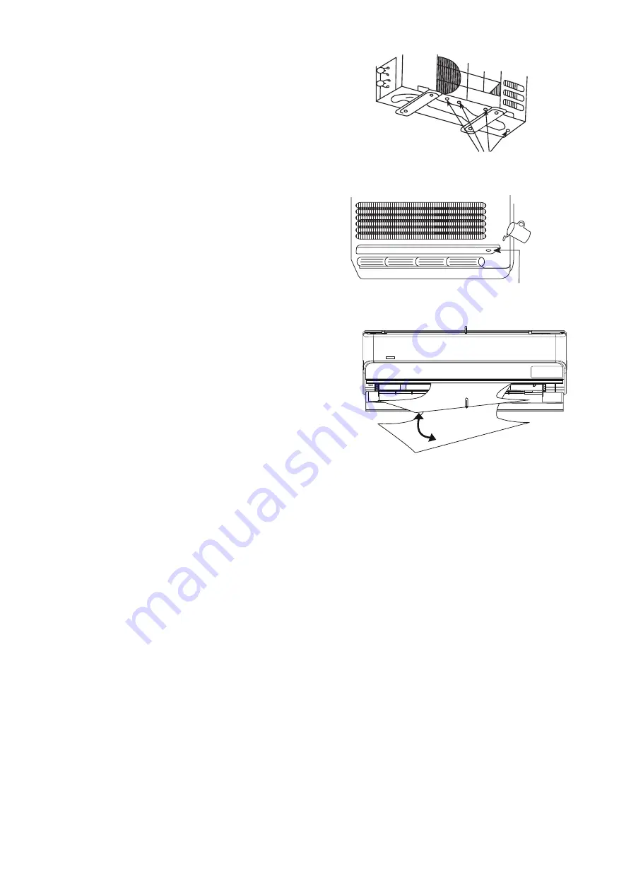
12.3.10  Check the Drainage 

  Open front panel and remove air filters. 

(Drainage checking can be carried out without 
removing the front grille.) 

  Pour a glass of water into the drain tray-styrofoam. 

  Ensure that water flows out from drain hose of the 

indoor unit. 


Drain tray-styrofoam


12.3.11  Evaluation of the Performance 

  Operate the unit at cooling/heating operation 

mode for fifteen minutes or more. 

  Measure the temperature of the intake and 

discharge air. 

  Ensure the difference between the intake 

temperature and the discharge is more than 8°C 
during Cooling operation or more than 14°C 
during Heating operation. 


Discharge air


Содержание CS-LZ25TKE

Страница 1: ...ry or death IMPORTANT SAFETY NOTICE There are special components used in this equipment which are important for safety These parts are marked by in the Schematic Diagrams Circuit Board Diagrams Exploded Views and Replacement Parts List It is essential that these critical parts should be replaced with manufacturer s specified parts to prevent shock fire or other hazards Do not modify the original d...

Страница 2: ...Operation Control 55 14 1 Basic Function 55 14 2 Indoor Fan Motor Operation 56 14 3 Outdoor Fan Motor Operation 58 14 4 Airflow Direction 59 14 5 Quiet Operation Cooling Mode Cooling Area of Dry Mode 61 14 6 Quiet Operation Heating 61 14 7 Powerful Mode Operation 61 14 8 Timer Control 62 14 9 Auto Restart Control 62 14 10 Indication Panel 62 14 11 8 15 C Heat Operation 63 15 Protection Control 64 ...

Страница 3: ...ing electric heater Else it may explode and cause injury or death 5 Do not tie up the power supply cord into a bundle by band Abnormal temperature rise on power supply cord may happen 6 Do not insert your fingers or other objects into the unit high speed rotating fan may cause injury 7 Do not sit or step on the unit you may fall down accidentally 8 The appliance shall be installed and or operated ...

Страница 4: ...ned after a long period the flare may break and cause refrigerant gas leakage 26 After completion of installation confirm there is no leakage of refrigerant gas It may generate toxic gas when the refrigerant contacts with fire 27 Ventilate if there is refrigerant gas leakage during operation It may cause toxic gas when the refrigerant contacts with fire 28 Be aware that refrigerants may not contai...

Страница 5: ...s are necessary to ensure that the risk of ignition is minimised For repair to the refrigerating system the precautions in 2 2 to 2 8 must be followed before conducting work on the system Work shall be undertaken under a controlled procedure so as to minimize the risk of a flammable gas or vapour being present while the work is being performed All maintenance staff and others working in the local ...

Страница 6: ...casing is not altered in such a way that the level of protection is affected This shall include damage to cables excessive number of connections terminals not made to original specification damage to seals incorrect fitting of glands etc Ensure that apparatus is mounted securely Ensure that seals or sealing materials have not degraded such that they no longer serve the purpose of preventing the in...

Страница 7: ...prior to leaving the site Electrostatic charge may accumulate and create a hazardous condition when charging and discharging the refrigerant To avoid fire or explosion dissipate static electricity during transfer by grounding and bonding containers and equipment before charging discharging 10 Decommissioning Before carrying out this procedure it is essential that the technician is completely famil...

Страница 8: ...equipment that is at hand and shall be suitable for the recovery of concerning the equipment that is at hand and shall be suitable for the recovery of flammable refrigerants In addition a set of calibrated weighing scales shall be available and in good working order Hoses shall be complete with leak free disconnect couplings and in good condition Before using the recovery machine check that it is ...

Страница 9: ...H L QLo Power Level dB 56 59 dB A 46 43 48 45 Cooling Outdoor Noise H L QLo Power Level dB 61 63 kW 0 85 3 20 6 55 0 85 4 20 7 65 BTU h 2900 10900 22300 2900 14300 26100 Capacity Kcal h 730 2750 5630 730 3610 6580 Running Current A 2 90 4 10 Input Power W 165 625 1 77k 165 890 2 30k W W 5 15 5 12 3 70 5 15 4 72 3 33 BTU hW 17 58 17 44 12 60 17 58 16 07 11 35 COP Kcal hW 4 42 4 40 3 18 4 42 4 06 2 ...

Страница 10: ...156 QLo Heat m 3 min ft 3 min 4 31 152 4 54 160 Cool m 3 min ft 3 min 5 11 180 5 68 201 Lo Heat m 3 min ft 3 min 6 93 245 7 05 249 Cool m 3 min ft 3 min 7 22 255 8 07 285 Me Heat m 3 min ft 3 min 9 61 339 9 84 347 Cool m 3 min ft 3 min 9 30 330 10 50 370 Hi Heat m 3 min ft 3 min 12 50 440 13 00 460 Cool m 3 min ft 3 min 9 90 350 11 04 390 Indoor Airflow SHi Heat m 3 min ft 3 min 13 55 478 14 00 49...

Страница 11: ...23 73 4 Cooling Maximum C F 16 60 8 11 51 8 16 60 8 11 51 8 Maximum C F 30 86 0 30 86 0 Heating Maximum C F 16 60 8 16 60 8 Maximum C F 15 59 0 15 59 0 Indoor Operation Range 8 15 C Heat Maximum C F 8 46 4 8 46 4 Maximum C F 43 109 4 26 78 8 43 109 4 26 78 8 Cooling Maximum C F 15 5 0 11 51 8 15 5 0 11 51 8 Maximum C F 24 75 2 18 64 4 24 75 2 18 64 4 Heating Maximum C F 20 4 0 20 4 0 Maximum C F O...

Страница 12: ...ection o Prevent compressor reverse cycle o Inner protector to protect compressor o Noise prevention during soft dry operation Operation Improvement o Quiet mode to reduce the indoor unit operating sound o Powerful mode to reach the desired room temperature quickly o 24 hour timer setting o 8 15 C HEAT operation is designed to provide heating at low temperature settings It is used in houses unoccu...

Страница 13: ...ion occurs Aluminium fin Air Purifying Filter Indicator POWER Green TIMER Orange DEICE Blue 8 15 C HEAT Green 5 2 Outdoor Unit 5 3 Remote Control Timer setting Airflow direction selection Fan speed operation Powerful Quiet operation Transmitter Operation mode 8 15 C Heat operation Remote control display Clock setting OFF ON Check Temperature setting ...

Страница 14: ...00 60 580 75 60 49 22 Remote Control 160 59 ON OFF SET TIMER CANCEL TEMP AIR SWING OFF ON MODE FAN SPEED AIR CONDITIONER Remote Control Holder 87 64 Rear View Relative position between the indoor unit and the installation plate Front View 450 174 166 22 63 200 49 Installation plate Indoor unit external dimensions line Unit mm 395 395 138 152 75 85 183 49 249 16 4 264 6 Gas side Liquid side ...

Страница 15: ...necessary for installation Anchor Bolt Pitch 330 x 540 Side View Side View Front View Top View Unit mm 2 way valve at Liquid side High Pressure 3 way valve at Gas side Low Pressure 1000 mm 100 mm 100 mm 540 21 9 124 68 5 824 97 167 330 32 53 4 160 ...

Страница 16: ...R TEMP SENSOR AIR TEMP SENSOR PIPE TEMP SENSOR 1 PIPE TEMP SENSOR 2 TANK SENSOR PIPE TEMP SENSOR LIQUID SIDE 2 WAY VALVE 3 WAY VALVE GAS SIDE COOLING HEAT EXCHANGER EVAPORATOR HEATING COMPRESSOR 4 WAYS VALVE CONDENSER MUFFLER MUFFLER STRAINER EXPANSION VALVE ...

Страница 17: ...ram FUSE 301 TEMPERATURE FUSE U SC M IC19 FUSE101 MS 3 REACTOR MS 3 NOISE FILTER FUSE103 SINGLE PHASE POWER SUPPLY FUSE104 C103 4 WAYS VALVE SC TH1 U NTC CT101 RY PWR RY AC PTC PTC1 3 2 1 INDOOR UNIT OUTDOOR UNIT L N ...

Страница 18: ... UPPER LEFT SUCTION TEMP SENSOR THERMISTOR PIPING TEMP SENSOR 2 THERMISTOR PIPING TEMP SENSOR 1 THERMISTOR 1 5 BR R O Y P M 1 5 BR R O Y P M 1 5 BR R O Y P W W W W W W W W W W 1 1 10 10 M 5 1 5 1 BR R O Y P M 5 1 BR R O Y P LEFT RIGHT LOUVER MOTOR UP DOWN LOUVER MOTOR LOWER RIGHT 1 3 1 4 1 10 12 1 2 2 1 W W WWW WW WW WW W W 1 10 12 CN CNT WHT CN FM WHT CN STM2 RED CN STM1 GRN VA1 U G BL W CN DISP2...

Страница 19: ...1 1 3 1 1 4 3 OUTDOOR AIR TEMP SENSOR THERMISTOR PIPING TEMP SENSOR THERMISTOR COMPRESSOR TEMP SENSOR THERMISTOR ELECTRO MAGNETIC COIL 4 WAY VALVE ELECTRO MAGNETIC COIL EXPANSION VALVE COMPRESSOR Q1 RED BLU YLW P U V W N U RED V BLU W YLW RAT2 GRY RAT1 GRY GRY GRY IC19 DATA RED AC BLK BLK AC WHT WHT FG1 GRN FG2 GRN HT2 BLU ACN2 BLU CN MTR2 WHT CN MTR1 WHT 1 1 5 3 W 10 14 16 U V 5 FAN MOTOR 1 3 BLU...

Страница 20: ...CN SW2 CN SW1 CN DISP1 White ELECTRONIC CONTROLLER DISPLAY ELECTRONIC CONTROLLER EMERGENCY SWITCH EMERGENCY OPERATION BUTTON SW401 ELECTRONIC CONTROLLER MAIN t t t 1 5V L351 L350 14V F350 32V R350 10k R353 10k C351 1000p 50V C350 1000p 50V C352 C353 5V R28 15k 1 C11 C12 C406 R29 20k 1 R404 20k 1 14V 14V 1 IC6 2 IC6 3 IC6 4 IC6 4 IC5 5 IC5 6 IC5 7 IC5 10 11 12 13 16 15 14 13 C8 R49 10k 5V 5V SW401 ...

Страница 21: ...P SENSOR THERMISTOR COMPRESSOR TEMP SENSOR THERMISTOR ELECTRO MAGNETI COIL 4 WAY VALVE ELECTRO MAGNETIC COIL EXPANSION VALVE COMPRESSOR Q1 RED BLU YLW P U V W N U RED V BLU W YLW RAT2 GRY RAT1 GRY GRY GRY IC19 DATA RED AC BLK BLK AC WHT WHT FG1 GRN FG2 GRN HT2 BLU ACN2 BLU CN MTR2 WHT CN MTR1 WHT 1 1 5 3 W 10 14 16 U V 5 FAN MOTOR 1 3 BLU BASE PAN HEATER BLU GRN GRN WHT BLK RED WHT BLK YLW GRN GRO...

Страница 22: ...22 11 Printed Circuit Board 11 1 Indoor Unit 11 1 1 Main Printed Circuit Board CN DISP1 CN SUB CN SW1 CN CNT CN FM CN STM1 JP1 Random Auto Restart enable disable CN STM2 CN TH2 CN TH1 ...

Страница 23: ...23 11 1 2 Indicator Printed Circuit Board LED201 LED203 LED204 LED202 LED205 CN DISP2 11 1 3 Switch Printed Circuit Board CN SW2 11 1 4 Sub Printed Circuit Board CN SUB CN STM9 CN STM7 CN STM8 ...

Страница 24: ...24 11 2 Outdoor Unit CN HOT CN STM CN TH1 CN MTR1 CN MTR2 CN TANK AC BLK DATA AC WHT POWER TRANSISTOR IPM CURRENT TRANSFORMER CT ...

Страница 25: ...ant should be 50 g 10 7 5 m 20 g m 50 g Amin M 2 5 LFL 5 4 h0 2 Amin Required minimum room area in m2 M Required charge amount in appliance in kg LFL Lower flammable limit 0 306 kg m3 h0 Installation height of the appliance 1 8 m for wall mounted 12 1 3 Indoor Outdoor Unit Installation Diagram d n e b o t t o n n o i t n e t t A n o i t c e r i d g n i p i P up drain hose Front side Right Right Re...

Страница 26: ... wall consider using anchor bolts o Always mount the installation plate horizontally by aligning the marking off line with the thread and using a level gauge 2 Drill the piping plate hole with ø70 mm hole core drill o Line according to the left and right side of the installation plate The meeting point of the extended line is the center of the hole Another method is by putting measuring tape at po...

Страница 27: ...tion of piping connection column as mentioned in indoor outdoor unit installation Step 8 Secure the Indoor Unit Cover for the bottom piping Cover for the bottom piping Tape it with piping in a position as mentioned in Fig below Cover for the right piping Piping Drain hose Cover for the left piping Right Rear piping Cover for the bottom piping Tape it with piping in a position as mentioned in Fig b...

Страница 28: ...or unit and outdoor unit shall be approved polychloroprene sheathed 4 1 5 mm2 flexible cord type designation 60245 IEC 57 or heavier cord Do not use joint connection cable Replace the wire if the existing wire from concealed wiring or otherwise is too short Allowable connection cable length of each indoor unit shall be 30 m or less 3 Bind all the indoor and outdoor connection cable with tape and r...

Страница 29: ...ires 12 2 4 2 Cutting and flaring the piping 1 Please cut using pipe cutter and then remove the burrs 2 Remove the burrs by using reamer If burrs is not removed gas leakage may be caused Turn the piping end down to avoid the metal powder entering the pipe 3 Please make flare after inserting the flare nut onto the copper pipes 1 To cut Improper flaring Inclined Surface damaged CrackedUneven thickne...

Страница 30: ... specified torque as stated in the table Torque wrench Spanner or Wrench For connection joint location at inside building Decide the length Cut and remove the tube connectors at indoor copper pipings both gas and liquid piping by using pipe cutter Remove burrs from cut edge Use pipe expander to expand the end of long piping Align the center of piping and braze the piping joints Indoor copper pipe ...

Страница 31: ...ose the Low side valve of the charging set and turn off the vacuum pump Make sure that the needle in the gauge does not move after approximately five minutes Note BE SURE TO TAKE THIS PROCEDURE IN ORDER TO AVOID REFRIGERANT GAS LEAKAGE 5 Disconnect the charging hose from the vacuum pump and from the service port of the 3 way valve 6 Tighten the service port caps of the 3 way valve at a torque of 1...

Страница 32: ...ss 4 Connect the power supply cord and connection cable between indoor unit and outdoor unit according to the diagram below Terminals on the indoor unit 1 2 3 1 2 3 Colour of wires connection cable Terminals on the outdoor unit L N Power supply cord Terminals on the isolating devices Disconnecting means L N 5 Secure the power supply cord and connection cable onto the control board with the holder ...

Страница 33: ...SE The Test Run operation will be activated if the Auto Switch is pressed continuously for more than 5 sec to below 8 sec A pep sound will occur at the fifth sec in order to identify the starting of Test Run operation 3 HEATING TRIAL OPERATION Press the AUTO switch continuously for more than 8 sec to below 11 sec and release when a pep pep sound is occured at eight sec However a pep sound is occur...

Страница 34: ... the front grille Pour a glass of water into the drain tray styrofoam Ensure that water flows out from drain hose of the indoor unit Drain tray styrofoam 12 3 11 Evaluation of the Performance Operate the unit at cooling heating operation mode for fifteen minutes or more Measure the temperature of the intake and discharge air Ensure the difference between the intake temperature and the discharge is...

Страница 35: ...In 2010 the regulations of American Society of Heating Refrigerating and Air Conditioning Engineers in the United States ANSI ASHRAE34 was issued adopting the grades for refrigerants which are difficult to inflame due to their slow burning rates and as a result have smaller damages in cases of fire The burning rate of R32 is lower by 10cm per second and safety standardization for various usage is ...

Страница 36: ...e of R410A it is necessary to do installation and service using high pressure tools and components Table 2 Saturated vapor pressure comparison table Unit MPa Refrigerant Temperature R32 R410A R22 20 0 30 0 30 0 14 0 0 71 0 70 0 40 20 1 37 1 35 0 81 40 2 38 2 32 1 43 60 3 84 3 73 2 33 65 4 29 4 17 2 60 Reference Thermal properties table of Japan Society of Refrigerating and Air Conditioning Enginee...

Страница 37: ...tools such as screw drivers metal saws electric drills long nose pliers hole core drills ø70 or ø65 linen tape levels temperature gauges clamp meters electric knives nippers pipe cutters reamers or scrapers spring benders diameters 1 4 3 8 1 2 5 8 monkey wrenches fixing wrenches 17 or 12 mm feeler gauges hexagon wrenches 4 mm testers megohm testers etc Tools used for services Works R32 R410A R22 I...

Страница 38: ...izes R32 common R410A R22 Port sizes 1 2 UNF20 7 16 UNF20 5 Charging hoses The pressure resistance of charge hoses is increased At the same time the material is changed to HFC resistant and the size of each manifold adopter is changed as the port size of manifold gauge itself Further some hoses are with anti gas pressure backflow valves placed near the adopters hoses with the valves recommended Ma...

Страница 39: ...ame time the digital scale for refrigerant charging is strengthened by receiving the weight of the refrigerant cylinders with four pillars at the corners The connection ports of charging hoses have two separate ports for R22 7 16 UNF20 and R32 R410A 1 2 UNF20 therefore they can be used for the insertion of the existing refrigerants Digital scale for refrigerant charging 9 Refrigerant cylinders Ref...

Страница 40: ...or each HCF type can be used Knowledge for the common usage of tools for R410A R32 R410A and R32 machines use different compressor oils If unregulated compressor oil gets mixed into it may cause damage to the machine function Careful pump down will ensure the recovery of compressor oil and it will minimize the remaining amount of the oil in the manifold gauge and charging hose If you only perform ...

Страница 41: ...vention of impurity Leakage checking Insertion of refrigerant Dismantling indoor outdoor units Repairing by brazing Evacuation Air purging new installation and relocation for at or more than 15 minutes re charging at or more than 60 minutes Indoor outdoor units and piping Displacing pipes and wires and displacing indoor outdoor units Indoor outdoor units installation and piping and wiring Removal ...

Страница 42: ... of moisture and dirt do not get into the pipes and make sure of no refrigerant leakage The procedure of flaring and precautions a Cutting of pipes use pipe cutter and cut the pipe slowly not to de shape the pipe b Removal of burrs on the edge of pipe reamer or scraper If the condition of pipe edge after the deburring is no good or if burrs attaches on the flaring it may cause refrigerant leakage ...

Страница 43: ...nd leave it for 1 2 minutes Then remove the connection side of the charging hose of vacuum pump adopter after checking the needle of manifold gauge does not turn back 4 Open the stem of 2 way valve to 90 in anti clock wise and close the 2 way valve after 10 seconds and perform gas leakage test 5 Remove the charge hose from the service port of 3 way valve and open the stems of 2 way and 3 way valve...

Страница 44: ...ly loosen the charging hose in discharging side of recovery device and perform air purge the recovery cylinder needs slight inside pressure 7 Insert electric plug of recovery device into electrical outlet the fan operation starts 8 Turn the valve 1 and 2 of recovery device to pressure equalization point 9 After a few seconds turn back the valve 1 and 2 to the original position 10 Turn the switch o...

Страница 45: ...tach and tighten the caps of two way and three way valves with torque wrench 6 Remove the connecting pipes liquid side and gas side b Removal of indoor and outdoor units 1 Remove the connecting pipes and wires between the indoor and outdoor units 2 Attach capping flare nuts on the edges of the pipes connecting the indoor and outdoor units in order to prevent dust and moisture get into the pipes 3 ...

Страница 46: ...ures below 6 Remove the charging hose red of the manifold gauge from the vacuum pump adopter 7 After adjusting the digital scale to zero open the cylinder valve and the valve Lo of the manifold gauge and insert the refrigerant 8 If it is not possible to insert the refrigerant at regulated amount at once operate the cooling mode and gradually insert the refrigerant recommended amount approx 150 g 1...

Страница 47: ...side check and make sure no refrigerant is contained in the air be careful with vaporized refrigerant Furthermore protect the compressor terminal with metal plates and heat but use wet clothes to cool down releasing the heat the expansion valves and four way valves prevent destruction of parts In brazing it is important to pour the brazing material without melting the base metal based on capillary...

Страница 48: ...rm the provision of gas 1 Slightly open the propane valve of the torch and make sure the gas comes out from the torch crater and then close the propane valve 2 Slightly open the oxygen valve of the torch and make sure the gas comes out from the torch crater and then close the oxygen valve Check there is no gas leakage around the hose connection 13 7 4 Adjustment of flame 1 Slightly open the propan...

Страница 49: ...r flame Blue color Oxidizing Flame Oxygen is more compared to the neutral flame Although the flame size is small this has the highest flame heat However due to the excessive oxygen contained in the flame the brazing point gets oxidized This flame may cause holes due to the high heat The pipe may get melt White core flame Outer flame Blue orange color 13 7 6 Closing the flame In case of short break...

Страница 50: ...resistance in stainless steel based brazing suitable for brazing tungsten carbide aluminum bronze and copper BCuP 2 remain 6 8 7 5 approx 710 approx 785 690 815 21 24 5 Cu Good liquidity suitable for brazing copper tube BCuP 3 4 8 5 2 remain 5 8 6 7 approx 645 approx 815 720 815 21 24 5 Cu Suitable for brazing when the joint spacing is not constant BCuP BCuP 5 14 5 15 5 remain 4 8 5 3 approx 645 a...

Страница 51: ...n Further by bending the brazing portion of dryer side of the capillary tube at 15 mm from the tube top to the angle of about 120 you can prevent the damage of dryer inside and the clogging of brazing material caused by the excessive insertion of capillary tube Gap 0 025 0 05 mm Insert diameter 10 25 mm Inner diameter ø6 45 Outer diameter ø6 35 Brazing material Runny Brazing material Hard to flow ...

Страница 52: ... capillary tube and dryer etc caution has to be taken to apply the flame to the dryer side thick pipe side in order to prevent burn out by the heat 4 When brazing the compressor connection pipes suction and discharge remove the sound insulation plate and the fan and place the compressor stand vertically to prevent the leakage of compressor refrigerating machine oil and apply the flame from the com...

Страница 53: ...an obstructing heat suction 3 Is the setting temperature on the remote controller correct is the setting temperature set at lower higher than the room temperature 13 8 2 Understanding and verification of refrigerant cycle Heat exchanger Heat exchanger Compressor COMP 4 way valve Condenser COND Expansion valve Liquid side 2 way valve Gas side 3 way valve High temp High pressure Air Mid temp High pr...

Страница 54: ...of refrigerant Clogged capillary expansion valve malfunction Heat releasing obstruction Clog by moisture Dirty condenser attachment of impurity Lack of refrigerant gas Refrigerant pressure Compressor malfunction Excess insertion of refrigerant Lack of refrigerant gas Heat releasing obstruction Compressor malfunction Dirty condenser impurity Mixture of air Operation electric current Insufficient ev...

Страница 55: ...tting temperature and it is updated continuously whenever the electrical power is supplied to the unit 14 1 2 Cooling Operation 14 1 2 1 Thermostat control Compressor is OFF when Intake Air Temperature Internal Setting Temperature 1 5 C continue for 3 minutes When compressor is OFF Thermostat OFF and AUTO FAN is set the fan will stop periodically Compressor is ON after waiting for 3 minutes if the...

Страница 56: ...nwards o If indoor intake temperature remote control setting temperature 3 C if previous operate in DRY mode then continue in DRY mode otherwise COOL mode is decided o If 2 C indoor intake temperature remote control setting temperature 3 C maintain with previous mode o If indoor intake temperature remote control setting temperature 2 C HEAT mode is decided 14 1 6 Fan Operation Fan Operation is use...

Страница 57: ...f the fan stop periodically Heating According to indoor pipe temperature automatic heating fan speed is determined as follows 41 38 B Feedback control Immediately after the fan motor started feedback control is performed once every second During fan motor on if fan motor feedback 2550 rpm or 50 rpm continue for 10 seconds then fan motor error counter increase fan motor is then stop and restart If ...

Страница 58: ...g cooling operation and outdoor ambient temperature is below 8 C outdoor fan speed will be controlled according to outdoor piping temperature as following OD Pipe Temperature A 25 C B 28 C During above condition when indoor heat exchanger temperature is below 5 C the outdoor fan will stop according to outdoor piping temperature as following ...

Страница 59: ...tion Step 1 Step 2 Step 3 Step 4 Step 5 Usual Ventilation 15 degrees 50 degrees Auto Control with dew 15 degrees 50 degrees Usual Ventilation 15 25 32 45 50 Cooling Manual Control with dew 15 25 32 45 50 Usual 15 degrees 50 degrees Auto Control with dew 15 degrees 50 degrees Usual 15 25 32 45 50 Dry Manual Control with dew 15 25 32 45 50 Manual 28 35 46 53 66 A zone 41 B zone 51 Heating Auto C zon...

Страница 60: ...s Figure 1 below It does not swing during fan motor stop Operation Mode Vane Angle A 50 130 Heating with heat exchanger temperature B 90 Cooling and soft dry 50 130 Manual horizontal airflow direction can be set using remote control the angles of the vane are as stated below and the positions of the vane are as Figure 2 above Pattern 1 2 3 4 5 Airflow Direction Patterns at Remote Control Vane Angl...

Страница 61: ...t heating operation compare to normal operation Control condition o Quiet operation start condition When POWERFUL QUIET button at remote control is pressed twice QUIET will be shown on remote control display o Quiet operation stop condition When one of the following conditions is satisfied quiet operation stops POWERFUL QUIET button is pressed again Stop by OFF ON switch Timer off activates 8 15 C...

Страница 62: ...14 8 2 OFF Timer Control OFF timer 1 and OFF timer 2 can be set using remote control the unit with timer set will stop operate at set time 14 9 Auto Restart Control When the power supply is cut off during the operation of air conditioner the compressor will re operate within three to four minutes there are 10 patterns between 2 minutes 58 seconds and 3 minutes 52 seconds to be selected randomly af...

Страница 63: ...fter battery reset default condition set temperature always start with 13 0 C OFF timer activates OFF timer activates OFF timer activates ON timer activates OR ON timer activates OR ON timer activates OR OR OR OR OR OR 1 Summer house set temperature follows previously fixed set temperature 8 0 C 15 0 C Transmit 8 15 C HEAT Go back to previous LCD setting tranmit code Go back to previous LCD settin...

Страница 64: ...A will be applied 15 1 3 IPM Power transistor Prevention Control Overheating Prevention Control 1 When the IPM temperature rises to 120 C compressor operation will stop immediately 2 Compressor operation restarts after 3 minutes the temperature decreases to 110 C 3 If this condition repeats continuously 4 times within 20 minutes timer LED will be blinking F96 is indicated DC Peak Current Control 1...

Страница 65: ...r suction is under 5 C Control contents o Compressor stops and restart after 3 minutes o If the conditions above happen 2 times within 20 minutes the unit will Stop operation Timer LED blinks and F91 indicated 15 1 6 Low Frequency Protection Control 1 When the compressor operate at frequency lower than 24 Hz continued for 20 minutes the operation frequency will be changed to 23 Hz for 2 minutes 15...

Страница 66: ...hanger is higher than 5 C At the same time indoor fan speed will be higher than during its normal operation If indoor heat exchanger temperature is higher than 5 C for 5 minutes the fan speed will return to its normal operation 15 2 4 Freeze Prevention Control 2 Control start conditions o During Cooling operation and soft dry operation During thermo OFF condition indoor intake temperature is less ...

Страница 67: ...erature Control Compressor will operate at limited freq if indoor intake air temperature is 30 C or above 15 3 2 Outdoor Air Temperature Control The Max current value is regulated when the outdoor air temperature rise above 14 C in order to avoid compressor overloading 15 3 3 Overload Protection Control The compressor operating frequency is regulated in accordance to indoor heat exchanger temperat...

Страница 68: ...pit The unit will enter into Operation Time Check Mode if the Emergency SW is pressed and held for at least 5 seconds before releasing within 5 minutes after Force Heating Operation begins Code receiving sound peet The unit will enter into Forced Cooling Operation again if the Emergency SW is pressed and held for at least 5 seconds before releasing within 5 minutes after Operation Time Check Mode ...

Страница 69: ...s Auto OFF ON button to toggle remote control receiving sound o Short beep Turn OFF remote control receiving sound o Long beep Turn ON remote control receiving sound After Auto OFF ON Button is pressed the 20 seconds counter for Remote Control Receiving Sound OFF ON Mode is restarted 16 2 Remote Control Button 16 2 1 SET Button To check remote control transmission code and store the transmission c...

Страница 70: ...ol Enable Press SW to enter customer zone press SW s to choose function 10 1 Press SW special setting is immediately cancelled and normal mode starts 2 If no SW is pressed for 30secs then special setting mode is cancelled and normal mode starts 3 Under this function only SW s are effective Note By default is enable ...

Страница 71: ...ement 16 2 2 RESET RC To clear and restore the remote control setting to factory default o Press once to clear the memory 16 2 3 RESET AC To restore the unit s setting to factory default o Press once to restore the unit s setting 16 2 4 TIMER To change indoor unit indicator s LED intensity o Press continuously for 5 seconds 16 2 5 TIMER To change remote control display from Degree Celsius C to Deg...

Страница 72: ...nd a fan The normal outlet air temperature and pressure of the refrigeration cycle depends on various conditions the standard values for them are shown in the table on the right Normal Pressure and Outlet Air Temperature Standard Gas Pressure MPa kg cm 2 G Outlet air Temperature C Cooling Mode 0 9 1 2 9 12 13 17 Heating Mode 2 0 2 7 20 27 32 42 Condition Indoor fan speed High Outdoor temperature 3...

Страница 73: ...e Electric current during operation Low Pressure High Pressure Electric current during operation Insufficient refrigerant gas leakage Clogged capillary tube or Strainer Short circuit in the indoor unit Heat radiation deficiency of the outdoor unit Inefficient compression Carry out the measurement of pressure electric current and temperature fifteen minutes after an operation is started ...

Страница 74: ...eration 1 Turn power on 2 Press the CHECK button on the remote controller continuously for 5 seconds 3 will be displayed on the remote controller display Note Display only for No transmitting signal no receiving sound and no Power LED blinking 4 Press the TIMER or button on the remote controller The code H00 no abnormality will be displayed and signal will be transmitted to the main unit The power...

Страница 75: ...ality Port is ON for 10s during ion device off ion device PCB H27 Outdoor air temperature sensor abnormality Continuous for 5s Outdoor air temperature sensor open or short circuit Outdoor air temperature sensor lead wire and connector H28 Outdoor heat exchanger temperature sensor 1 abnormality Continuous for 5s Outdoor heat exchanger temperature sensor 1 open or short circuit Outdoor heat exchange...

Страница 76: ...door standby units freezing abnormality 3 times happen within 40 minutes Wrong wiring and connecting pipe expansion valve leakage indoor heat exchanger sensor open circuit Check indoor outdoor connection wire and pipe Indoor heat exchanger sensor lead wire and connector Expansion valve lead wire and connector F90 Power factor correction PFC circuit protection 4 times happen within 10 minutes Power...

Страница 77: ...ived from outdoor unit in indoor unit signal transmission is checked whether it is normal Malfunction Caused Faulty indoor unit PCB Faulty outdoor unit PCB Indoor unit outdoor unit signal transmission error due to wiring error Indoor unit outdoor unit signal transmission error due to breaking of wire in the connection wires between the indoor and outdoor units Troubleshooting ...

Страница 78: ...are interconnected Malfunction Caused Wrong models interconnected Wrong indoor unit or outdoor unit PCBs mounted Indoor unit or outdoor unit PCBs defective Indoor outdoor unit signal transmission error due to wrong wiring Indoor outdoor unit signal transmission error due to breaking of wire 3 in the connection wires between the indoor and outdoor units Troubleshooting ...

Страница 79: ...ction Decision Conditions During startup and operation of cooling and heating the temperatures detected by the indoor intake air temperature sensor are used to determine sensor errors Malfunction Caused Faulty connector connection Faulty sensor Faulty PCB Troubleshooting ...

Страница 80: ...n Decision Conditions During startup and operation of cooling and heating the temperatures detected by the outdoor compressor temperature sensor are used to determine sensor errors Malfunction Caused Faulty connector connection Faulty sensor Faulty PCB Troubleshooting ...

Страница 81: ...ion Conditions An input current detected by Current Transformer CT is below threshold value when the compressor is operating at certain frequency value for 3 minutes Malfunction Caused Lack of gas Broken CT current transformer Broken Outdoor PCB Troubleshooting ...

Страница 82: ...termine abnormal fan motor feedback of rotation 2550 rpm or 50 rpm Malfunction Caused Operation stops due to short circuit inside the fan motor winding Operation stops due to breaking of wire inside the fan motor Operation stops due to breaking of fan motor lead wires Operation stops due to Hall IC malfunction Operation error due to faulty indoor unit PCB Troubleshooting ...

Страница 83: ... Decision Conditions During startup and operation of cooling and heating the temperatures detected by the indoor heat exchanger temperature sensor are used to determine sensor errors Malfunction Caused Faulty connector connection Faulty sensor Faulty PCB Troubleshooting ...

Страница 84: ...ction Decision Conditions During startup and operation of cooling and heating the temperatures detected by the outdoor air temperature sensor are used to determine sensor errors Malfunction Caused Faulty connector connection Faulty sensor Faulty PCB Troubleshooting ...

Страница 85: ...ction Decision Conditions During startup and operation of cooling and heating the temperatures detected by the outdoor pipe temperature sensor are used to determine sensor errors Malfunction Caused Faulty connector connection Faulty sensor Faulty PCB Troubleshooting ...

Страница 86: ...tion Decision Conditions During startup and operation of cooling and heating the temperatures detected by the outdoor discharge pipe temperature sensor are used to determine sensor errors Malfunction Caused Faulty connector connection Faulty sensor Faulty PCB Troubleshooting ...

Страница 87: ...nction Decision Conditions During startup and operation of cooling and heating the temperatures detected by the outdoor heat exchanger temperature sensor are used to determine sensor errors Malfunction Caused Faulty connector connection Faulty sensor Faulty PCB Troubleshooting ...

Страница 88: ...alfunction Decision Conditions The supply power is detected for its requirement by the indoor outdoor transmission Malfunction Caused Wrong models interconnected Wrong indoor unit and outdoor unit PCBs used Indoor unit or outdoor unit PCB defective Troubleshooting ...

Страница 89: ...ction Decision Conditions During startup and operation of cooling and heating the temperatures detected by the outdoor heat sink temperature sensor are used to determine sensor errors Malfunction Caused Faulty connector connection Faulty sensor Faulty PCB Troubleshooting ...

Страница 90: ...Decision Conditions During startup and operation of cooling and heating the temperatures detected by the outdoor gas pipe temperature sensor are used to determine sensor errors Malfunction Caused Faulty connector connection Faulty sensor Faulty PCB Troubleshooting ...

Страница 91: ...ction Decision Conditions During startup and operation of cooling and heating the temperatures detected by the outdoor liquid pipe temperature sensor are used to determine sensor errors Malfunction Caused Faulty connector connection Faulty sensor Faulty PCB Troubleshooting ...

Страница 92: ...power supply and rotate fan by hand Does it rotate CN MTR2 WHT IC19 3 5 1 10 14 16 W U V FAN MOTOR MS CN MTR1 PCB BOARD 5 4 3 2 1 C173 5V R105 1k C176 0 01µ 50V G5 R111 1k C177 0 01µ 50V G5 R120 1k C175 0 01µ 50V G5 G5 YES NO YES Turn off power supply and disconnect fan motor CN MRT2 Check resistance of the motor Measure at fan motor connector CN MRT1 1 2 1 3 2 3 Replace outdoor PCB NO Replace fan...

Страница 93: ...h pressure is detected when indoor heat exchanger is detecting very high temperature when the unit is operating in heating operation Phenomena unit is stopping and re starting very often in heating mode Malfunction Caused Indoor heat exchanger thermistor Clogged air filter or heat exchanger Over bent pipe liquid side Troubleshooting ...

Страница 94: ...l takes place when indoor pipe temperature is lower than 2 C Malfunction Caused Air short circuit at indoor unit Clogged indoor unit air filter Dust accumulation on the indoor unit heat exchanger 2 3 way valve closed Faulty indoor unit fan motor Refrigerant shortage refrigerant leakage Clogged expansion valve or strainer Faulty indoor pipe temperature sensor Faulty indoor unit PCB Troubleshooting ...

Страница 95: ...is cold during heating except deice or when indoor heat exchanger is hot during cooling and compressor operating the 4 way valve is detected as malfunction Malfunction Caused Indoor heat exchanger pipe thermistor 4 way valve malfunction Troubleshooting Check gas side pipe for hot gas flow in cooling mode ...

Страница 96: ...rature and indoor pipe temperature is above 10 C or indoor pipe temperature is below 1 0 C Remark When the indoor standby unit is freezing the outdoor unit transfers F17 error code to the corresponding indoor unit and H39 to other indoor unit s Malfunction Caused Wrong wiring connection Faulty sensor Faulty expansion valve Troubleshooting ...

Страница 97: ...startup and operation of cooling and heating when Power Factor Correction PFC protection circuitry at the outdoor unit main PCB senses abnormal DC voltage level for power transistors When DC voltage detected is LOW transistor switching will turn ON by controller to push up the DC level When DC voltage detected is HIGH 391Vdc 425Vdc active LOW signal will send by the controller to turn OFF relay RY...

Страница 98: ...rigeration Cycle Abnormality Malfunction Decision Conditions The input current is low while the compressor is running at higher than the setting frequency Malfunction Caused Lack of gas 3 way valve close Troubleshooting ...

Страница 99: ...ion Decision Conditions A compressor rotation failure is detected by checking the compressor running condition through the position detection circuit Malfunction Caused Compressor terminal disconnect Faulty Outdoor PCB Faulty compressor Troubleshooting ...

Страница 100: ...y the outdoor unit heat exchanger thermistor Malfunction Caused Outdoor heat exchanger temperature rise due to short circuit of hot discharge air flow Outdoor heat exchanger temperature rise due to defective of outdoor fan motor Outdoor heat exchange temperature rise due to defective outdoor heat exchanger thermistor Outdoor heat exchanger temperature rise due to defective of outdoor unit PCB Trou...

Страница 101: ...ted o Heat Sink Overheating During operation of cooling and heating when heat sink temperature data 90 C is detected by the heat sink temperature sensor Malfunction Caused IPM overheats due to short circuit of hot discharge air flow IPM overheats due to defective of outdoor fan motor IPM overheats due to defective of internal circuitry of IPM IPM overheats due to defective IPM temperature sensor M...

Страница 102: ...ling and heating when compressor tank temperature data 112 C is detected by the compressor tank temperature sensor Malfunction Caused Faulty compressor tank temperature sensor 2 3 way valve closed Refrigerant shortage refrigerant leakage Faulty outdoor unit PCB Faulty compressor Troubleshooting ...

Страница 103: ...ion of cooling and heating when an input over current X value in Total Running Current Control is detected by checking the input current value being detected by current transformer CT with the compressor running Malfunction Caused Excessive refrigerant Faulty outdoor unit PCB Troubleshooting ...

Страница 104: ...heating when inverter DC peak data is received by the outdoor internal DC Peak sensing circuitry Malfunction Caused DC current peak due to compressor failure DC current peak due to defective power transistor s DC current peak due to defective outdoor unit PCB DC current peak due to short circuit Troubleshooting ...

Страница 105: ...on may result in electric shocks 18 1 Indoor Electronic Controllers Cross Flow Fan and Indoor Fan Motor Removal Procedures 18 1 1 Air Filters Removal Procedures Intake Grille Decoration Base Figure 1 Air Filters 1 Lift up the intake grille with both hands Note Hold the grooves on both side of intake grille to lift it up Groove 2 Pull down the Decoration Base 3 Release the hooks by slightly lift up...

Страница 106: ...mplete Removal Procedures 1 Push the intake grille further up then pull it towards you to remove it Figure 3 Screws and Caps 2 Remove the caps and screw from the Bottom Plate Then pull out the Bottom Plate Bottom Plate Figure 4 ...

Страница 107: ...the bottom plate then attached the back hooks left and right and center hook to its position Then press firmly until the front hooks attached properly Note Front Grille Complete Screws Screws 3 Remove 4 screws then pull out the Front Grille Complete Air Filter Frame Figure 5 ...

Страница 108: ...8 18 1 3 Indoor Main Electronic Controller Removal Procedures Screws 1 Remove 2 screws from the right side of Front Grille Complete Figure 6 Control board Terminal Board Cover Control Board Cover Figure 7 ...

Страница 109: ...109 2 Remove 1 screw from the control board 3 Detach the earth wire from the control board Figure 8 4 Slightly pull out the control board Figure 9 ...

Страница 110: ...rol board cover by releasing 5 hooks Figure 10 8 Detach lead wires AC1 Black and AC3 Red from the terminal board 7 Remove the terminal board cover Figure 11 9 Remove all connectors form the PCB Then pull out the Indoor Main Electronic Controller Indoor Main Electronic Controller Figure 12 ...

Страница 111: ... Controller Removal Procedures 1 Remove 2 screws from the left side of Front Grille Complete Hooks 2 Release 3 hooks then remove the control board cover Hook Figure 13 3 Remove all connectors then take out the sub PCB Figure 14 ...

Страница 112: ...ose 1 Remove a screw from the drain hose Note PLEASE USE WRENCH 7mm OR RATCHET TO LOOSEN THIS SCREW Figure 15 Air Filter Frame 2 Remove 2 screws from the right side of the Air Filter Frame Figure 16 3 Remove 2 screws from the left side of Air Filter Frame Figure 17 ...

Страница 113: ...arge Grille Complete Then pull out the Discharge Grille Figure 18 18 1 6 Cross Flow Fan Removal Procedures 1 Remove 2 screws form the Evaporator 2 Remove screw from Cross Flow Fan Figure 19 Evaporator Cross Flow Fan 3 Lift up the evaporator 4 Pull out the Cross Flow Fan Figure 20 ...

Страница 114: ...114 18 1 7 Fan Motor Removal Procedures Particular Plate 1 Remove 4 screws from the Particular Plate Figure 21 Fan Motor 2 Pull out the Fan Motor to remove it Figure 22 ...

Страница 115: ...ller be careful of electrostatic discharge 1 Remove the 5 screws of the Top Panel Fig 1 2 Remove the 8 screws of the Front Panel Fig 2 3 Remove the screw of the Terminal Board Cover 4 Remove the Top Cover of the Control Board by 4 hooks Fig 3 5 Remove the Control Board as follows Fig 4 Fig 5 Fig 6 ...

Страница 116: ...3 15 7 2080 1715 101 1850 1541 138 2531 2037 256 2639 1416 314 23 18 4 2132 1256 108 1372 707 121 2662 1300 223 2901 1269 325 13 3 1847 1563 108 1690 1474 136 1906 1567 125 2061 1655 204 20 15 8 1913 1218 110 1718 1140 119 2394 1375 250 2651 1228 334 Indoor C Outdoor DB C 16 25 35 DB WB TC SHC IP TC SHC IP TC SHC IP 19 0 2953 1930 297 2764 1790 392 2500 2063 505 27 22 0 3336 1493 287 3040 1732 394...

Страница 117: ...82 2365 2063 230 2669 2193 212 2885 2317 346 20 15 8 2679 1706 186 2405 1596 201 3351 1925 424 3711 1719 565 Indoor C Outdoor DB C 16 25 35 DB WB TC SHC IP TC SHC IP TC SHC IP 19 0 4134 2702 502 3870 2506 663 3500 2506 855 27 22 0 4670 2090 486 4257 2425 667 3956 1907 860 15 7 3771 2686 516 3506 2572 667 3209 2325 848 23 18 4 4082 2219 508 3844 2131 663 3409 1903 855 13 3 2937 2371 349 3336 2625 6...

Страница 118: ...7 3873 1686 3843 1472 4485 1499 5864 1733 Indoor C Outdoor WB C 12 11 DB TC IP 24 5462 1709 20 5859 1730 16 6233 1732 19 2 2 CS LZ35TKE CU LZ35TKE Indoor C Outdoor WB C 20 21 15 16 7 8 2 1 7 6 DB TC IP TC IP TC IP TC IP TC IP 24 3426 1975 4156 2094 4151 1978 4558 1946 6054 2183 20 3515 1859 46 4263 1972 4370 1918 4986 1935 6503 2182 16 3562 1789 4320 1897 4420 1815 5230 1949 6849 2180 Indoor C Out...

Страница 119: ...ir Temperature C Current Cool Current A 1 800 1 980 2 160 2 340 2 520 2 700 16 17 18 19 20 21 22 23 24 25 26 27 28 29 30 31 32 33 34 35 36 37 38 39 40 41 42 43 Outdoor Air Temperature C Lo Pressure Cool Lo Pressure MPa 0 920 0 956 0 992 1 028 1 064 1 100 16 17 18 19 20 21 22 23 24 25 26 27 28 29 30 31 32 33 34 35 36 37 38 39 40 41 42 43 Outdoor Air Temperature C Outlet air Cool Indoor Discharge Ai...

Страница 120: ...40 41 42 43 Outdoor Air Temperature C Lo Pressure Cool Lo Pressure MPa 0 800 0 840 0 880 0 920 0 960 1 000 16 17 18 19 20 21 22 23 24 25 26 27 28 29 30 31 32 33 34 35 3637 38 39 40 41 42 43 Outdoor Air Temperature C Outlet Air Cool Indoor Discharge Air Temperature C 9 700 10 480 11 260 12 040 12 820 13 600 16 17 18 19 20 21 22 23 24 25 26 27 28 29 30 31 32 33 34 35 36 37 38 39 40 41 42 43 ...

Страница 121: ...LZ25TKE Outdoor Air Temperature C Current Heat Current A 1 400 1 700 2 000 2 300 2 600 2 900 20 17 14 11 8 5 2 1 4 7 Outdoor Air Temperature C Hi Pressure Heat Hi Pressure MPa 1 300 1 480 1 660 1 840 2 020 2 200 20 17 14 11 8 5 2 1 4 7 Outdoor Air Temperature C Outlet Air Heat Indoor Discharge Air Temperature C 19 000 22 000 25 000 28 000 31 000 34 000 20 17 14 11 8 5 2 1 4 7 ...

Страница 122: ... 300 3 700 4 100 20 17 14 11 8 5 2 1 4 7 Outdoor Air Temperature C Hi Pressure Heat Hi Pressure MPa 1 500 1 660 1 820 1 980 2 140 2 300 20 17 14 11 8 5 2 1 4 7 Outdoor Air Temperature C Outlet Air Heat Indoor Discharge Air Temperature C 21 900 24 880 27 860 30 840 33 820 36 800 20 17 14 11 8 5 2 1 4 7 ...

Страница 123: ...CU LZ35TKE 0 94 0 95 0 96 0 97 0 98 0 99 1 00 1 01 1 02 2 3 4 5 6 7 8 9 10 11 12 13 14 15 16 17 18 19 20 21 22 Correction Factor Pipe Length m Cooling Capacity 0 90 0 95 1 00 1 05 1 10 2 3 4 5 6 7 8 9 10 11 12 13 14 15 16 17 18 19 20 21 22 Correction Factor Pipe Length m Heating Capacity Note The graphs show the factor after added right amount of additional refrigerant ...

Страница 124: ...7 21 20 10 17 16 9 23 13 43 31 32 38 28 44 45 24 22 42 40 41 14 15 12 11 30 18 19 O N O FF SET TIMER CANCEL TEMP AIR SWIN G OFF ON MOD E FAN SPEED AIR CON DITION ER Note The above exploded view is for the purpose of parts disassembly and replacement The non numbered parts are not kept as standard service parts ...

Страница 125: ...00010 18 VERTICAL VANE RIGHT 1 ACXE24C00020 19 STEPPING MOTOR VERTICAL VANE 1 L6JAYYYH0079 O 20 CAP DRAIN TRAY 1 CWH521096 21 FULCRUM 1 ACXH62 00030 22 ELECTRONIC CONTROLLER MAIN 1 ACXA73 18321 O 23 TERMINAL BOARD COMPLETE 1 ACXA28C03650 A28K1110J O 24 ELECTRONIC CONTROLLER SWITCH 1 ACXA73 18620 O 25 SENSOR COMPLETE 1 ACXA50C06740 O 26 PLATE SPRING 1 CWH711019 27 INTAKE GRILLE COMPLETE 1 ACXE22C00...

Страница 126: ...BOARD COMPLETE SUB 1 ACXH10C32360 42 DUCT COMPLETE 1 ACXD22C00010 B 43 AIR FILTER 2 CWD001307 44 AIR PURIFYING FILTER 1 CWD001274 45 REMOTE CONTROLLER 1 ACXA75C07870 O NOTE All parts are supplied from PAPAGZ China Vendor Code 00029059 O marked parts are recommended to be kept in stock ...

Страница 127: ... 8 7 5 6 4 11 33 28 34 19 1 10 39 49 48 51 14 38 50 18 23 52 53 57 12 O I 59 58 56 54 55 I I 63 I I 60 I I 61 I I 64 I I 62 Note The above exploded view is for the purpose of parts disassembly and replacement The non numbered parts are not kept as standard service parts ...

Страница 128: ...OVER 1 CWH7080300J 22 SOUND PROOF BOARD 1 CWH151273 23 SOUND PROOF MATERIAL COMP BODY 1 CWG302952 26 ELECTRONIC CONTROLLER MAIN 1 ACXA73C30280R ACXA73C30290R O 27 TERMINAL BOARD ASS Y 1 CWA28K1110J O 28 CABINET SIDE PLATE CO 1 CWE04C1481 29 SENSOR CO CN TH1 OUT PIPING TEMP 1 CWA50C3079 O 30 CABINET SIDE PLATE L 1 CWE041616A 31 CABINET FRONT PLATE CO 1 CWE06C1441 32 CABINET TOP PLATE 1 CWE031148A 3...

Страница 129: ...ON 1 ACXF55 11470 60 INSTALLATION INSTRUCTION 1 ACXF60 16960 61 INSTALLATION INSTRUCTION 1 ACXF60 16970 62 INSTALLATION INSTRUCTION 1 ACXF60 16980 63 INSTALLATION INSTRUCTION 1 ACXF60 16990 64 INSTALLATION INSTRUCTION 1 ACXF60 17000 NOTE All parts are supplied from PAPAMY Malaysia Vendor Code 00029488 O marked parts are recommended to be kept in stock Printed in Malaysia SB0817 1 ...

Отзывы: