


12
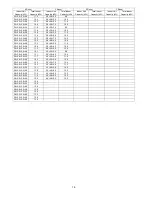
CONNECTABLE
INDOOR UNIT
OUTDOOR UNIT
CU-4E27PBE CU-5E34PBE
Type/ROOM
A B C D A B C D E
Wall
2.0kW
CS-E7PKEW
CS-XE7PKEW
●
●
●
●
●
●
●
●
●
2.5kW
CS-E9PKEW
CS-XE9PKEW
CS-ME9PD3EA
CS-ME9PB4EA
CS-E9GFEW
CS-E9GFEW-2
CS-E9PD3EA
CS-E9PB4EA
●
●
●
●
●
●
●
●
●
3.2kW
CS-E12PKEW
CS-XE12PKEW
CS-ME12PD3EA
CS-ME12PB4EA
CS-E12GFEW
CS-E12GFEW-2
CS-E12PD3EA
CS-E12PB4EA
●
●
●
●
●
●
●
●
●
4.0kW
CS-E15PKEW
CS-XE15PKEW
●
●
●
●
●
●
●
●
●
5.0kW
CS-E18PKEW
CS-XE18PKEW
CS-ME18PD3EA
CS-ME18PB4EA
CS-E18GFEW
CS-E18GFEW-2
●
●
●
●
●
●
●
●
●
6.0kW
CS-E21PKEW
CS-XE21PKEW
CS-ME21PB4EA
●
●
●
●
●
●
●
●
●
7.0kW CS-E24PKEW
●
●
●
●
●
●
●
●
●
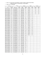
Capacity range of connectable
indoor units
From 4.5kW
to 13.6kW
From 4.5kW
to 17.5 kW
Pipe length
1 room maximum
pipe length (m)
25 25
Allowable elevation (m)
15
15
Total allowable pipe
length (m)
70 80
Total pipe length for
maximum chargeless
length (m)
45 45
Additional gas
amount over
chargeless length (g/m)
20 20
Note: “
●
” : Available
Remarks for CU-4E27PBE / CU-5E34PBE
1. At least two indoor units must be connected.
2. The total nominal cooling capacity of indoor units that will be connected to outdoor unit must be within
connectable capacity range of indoor unit. (as shown in the table above)
Example: The indoor units’ combination below is possible to connect to CU-4E27PBE.
(Total nominal capacity of indoor units is between 4.5kW to 13.6kW)
1) Two CS-E9PKEW only (Total nominal cooling capacity is 5.0kW)
2) Three CS-E12PKEW. (Total nominal cooling capacity is 9.6kW)
Содержание CS-E9PB4EA
Страница 24: ...24 4 Location of Controls and Components 4 1 Indoor Unit 4 2 Outdoor Unit 4 3 Remote Control...
Страница 25: ...25 5 Dimensions 5 1 Indoor Unit...
Страница 26: ...26 5 2 Outdoor Unit 5 2 1 CU E9PB4EA 5 2 2 CU E12PB4EA...
Страница 27: ...27 6 Refrigeration Cycle Diagram 6 1 CS E9PB4EA CU E9PB4EA...
Страница 28: ...28 6 2 CS E12PB4EA CU E12PB4EA...
Страница 29: ...29 7 Block Diagram 7 1 CS E9PB4EA CU E9PB4EA...
Страница 30: ...30 7 2 CS E12PB4EA CU E12PB4EA...
Страница 31: ...31 8 Wiring Connection Diagram 8 1 Indoor Unit...
Страница 34: ...34 9 Electronic Circuit Diagram 9 1 Indoor Unit...
Страница 35: ...35 9 2 Outdoor Unit 9 2 1 CU E9PB4EA...
Страница 36: ...36 9 2 2 CU E12PB4EA...
Страница 37: ...37 10 Printed Circuit Board 10 1 Indoor Unit 10 1 1 Main Printed Circuit Board...
Страница 38: ...38 10 1 2 Display Printed Circuit Board...
Страница 39: ...39 10 2 Outdoor Unit 10 2 1 CU E9PB4EA...
Страница 40: ...40 10 2 2 CU E12PB4EA...
Страница 65: ...65 14 3 2 CU E12PB4EA...
Страница 97: ...97 8 Remove the Fan Motor by release the Fan Motor lead wire connectors and Fan Motor screws Fig 8 Fig 8...
Страница 106: ...106 18 Exploded View and Replacement Parts List 18 1 Indoor Unit...


