57
47
E
N
G
L
I
S
H
48
E
N
G
L
I
S
H
56
CQ-VA7800N
CQ-VA7800N
ACC
BATTERY 15A
A
B
A8
(Black)
A7
(Red)
A4
(Yellow)
A5
(Blue)
B8
(Green/black stripe)
B7
(Green)
B6
(White/black stripe)
B5
(White )
B4
(Gray/black stripe)
B3
(Gray)
B2
(Violet/black stripe)
B1
(Violet )
Not used.
A5
: Motor Antenna Relay Control Lead
(Blue)
To Motor Antenna (Max. 500 mA).
This lead is not intended for use with a switch
actuated power antenna.
Note:
The power antenna extends automati-
cally when the power of this unit is turned on.
A7
: Power Lead (ACC or IGN)
(Red)
To ACC power, +12 V DC.
A8
: Ground Lead
(Black)
To a clean, bare metallic part of the car chassis.
A4
: Battery Lead
(Yellow)
To the car battery, cont12 V DC.
Reverse Lead
(Violet/white stripe)
When connecting the rear view camera, use the reverse lead.
Side Brake (Parking Brake) Connection Lead
(Blue/yellow stripe)
Be sure to wire the side brake (parking brake) for safety and pre-
venting accidents.
External Remote Control Lead
(Brown/black stripe)
When using non-Panasonic external remote control, refer to the
manufacture for their product before connecting.
External Amplifier Control Power Lead
(Blue/white stripe)
To an external amplifier.
TV Antenna
CL-T60EW
(option)
B2
B1
B4
B3
B5
B6
B7
B8
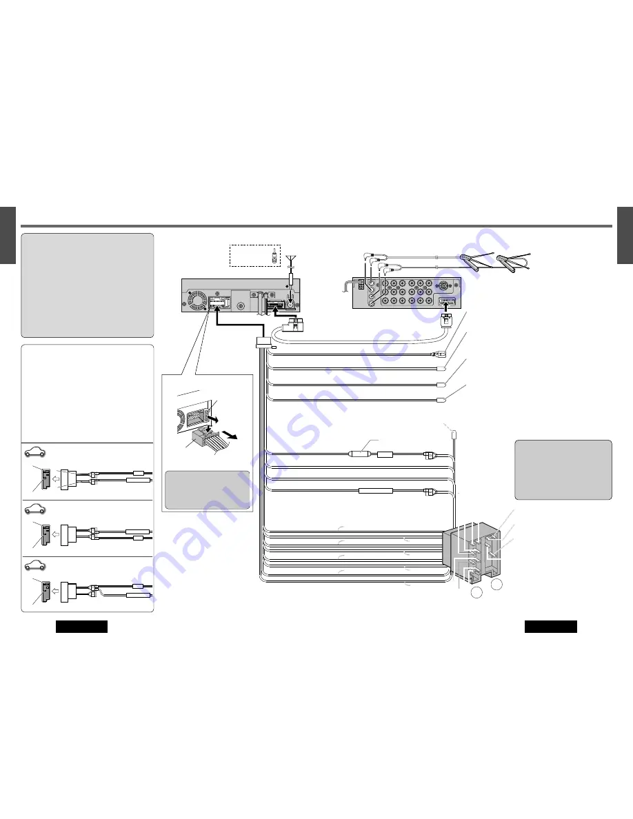
Electrical Connections
Cautions:
¡
Check the connectors provided on your car (see
precaution below) before connecting the system.
¡
This unit is designed for use in a car having a 12-
volt negative ground battery system.
¡
To prevent damage to the unit, be sure to follow
the connection diagram.
¡
Strip about 5 mm of the lead ends for connection
(only non-ISO connector cords).
¡
Do not insert the power connector into the unit
until the wiring is completed.
¡
Be sure to insulate any exposed wires to prevent
short circuiting with the car chassis. Bundle all
cables, and prevent cable terminals from touching
any metal parts.
Precautions (ISO Connector)
¡
The pin arrangement of the power connector
conforms to ISO standard.
¡
The pin arrangement of ISO connectors in some
cars may differ from the ISO standard.
¡
Please check that the pin arrangement of the
connector in your car conforms to ISO standard.
¡
For car types A and B, change the wiring of the
red and yellow leads as shown at below.
¡
After connection, insulate the portions marked
(
C
) with insulating tape.
Note:
For cars other than types A and B, please
consult your local car shop.
C
C
BATTERY 15A
ACC
C
C
BATTERY 15A
ACC
C
C
ISO
A
B
Standard ISO
Car Type A
Car Type B
BATTERY 15A
ACC
A7:
IGN or ACC switched 12 V supply
(Red)
(Yellow)
(Yellow)
(Red)
(Red)
(Yellow)
(Yellow)
(Red)
(Red)
(Yellow)
(Red)
(Yellow)
A4:
IGN or ACC switched 12 V supply
A4:
+12 V Battery (Permanent supply)
A7:
+12 V Battery (Permanent supply)
A7:
+12 V Battery (Permanent supply)
A4:
No connection
A7
A4
Wiring Diagram
CQ-VA7800N
Display Unit
CQ-VA7800N
Hide-away Unit
Antenna
To remove the Fuse...
3
1
2
If the fuse (rear panel) blows fre-
quently, they may be something
wrong with the unit. Contact the
shop where you purchased this
product.
Fuse (15 A)
@0
Power
Connector
Fuse (15 A)
@3
Display Unit/Hide-away Unit
Connecting Cord
@0
Power Connector
@4
ISO Antenna
Adapter
(If needed)
Resistor (220
Ω
)
B8
: Rear Left –
B7
: Rear Left +
B6
: Front Left –
B5
: Front Left +
B4
: Front Right –
B3
: Front Right +
B2
: Rear Right –
B1
: Rear Right +
Speakers
Cautions:
¡
Use ungrounded speakers only.
Allowable input : 50 W or more
Impedance : 4 – 8
Ω
¡
Distance between speaker and ampli-
fier: 30 cm or more
¡
Do not connect more than one speak-
er to one set of speaker leads. (except
for connecting to a tweeter)


