background image

Содержание CF-2700

Страница 1: ...al port Sound output Dimensions and Weight Main unit Power requirements Voltage Power consumption TMS 9929A 32 characters x 24 lines 8 H x 8 W dots character mode 40 characters x 24 lines 8 H x 6 W dots character mode 256 H x 192 V dots Video output RF output AY 3 8910A 8 octave 3 chord output 73 keys FSK 1200 2400 baud 2 comforms to MSX specifications 1 14 pin 2 9 pin each 1 436 W x 245 D x 90 H ...

Страница 2: ...t 64 Copyright Matsushita Electric Industrial Co Ltd 1984 The EE3 system realizes software compatibility between personal computers is a trademark of Microsoft Corporation IMPORTANT FOR U K The wires in the mains lead are coloured in accordance with the following codes Blue Neutral Brown Live As the colours of the wires in the mains lead of this apparatus may not correspond with the coloured marki...

Страница 3: ... located on the left side I fctr i ON POWER o OFF ...

Страница 4: ... to input a space between characters 3 Character keys Keys used to input characters 17 Channel adjust trimmer After connecting the TV and computer turn on the power switch Set the TV to UHF channels 35 37 Insert the adjustment screwdriver into the channel adjust trimmer and adjust for a clear picture 6 Cursor keys Keys used to move the cursor 7 General port 1 General port 2 Connectors used to conn...

Страница 5: ...tion Stack area storing the return address for BASIC when the FOR NEXT statement or GOSUB statement is executed Area storing the strings contained in the character variables and array variables The size of the string area is as specified in the CLEAR statement If no size is specified in the CLEAR statement an area of 200 bytes is allocated Area used during the input and output of files This area i...

Страница 6: ...present the system reserve area PSG Bit Assignment Port Bit I O Bit 6 at Port B Connector Pin Number A 0 Input Low level High level Port 1 pin 1 Port 2 pin 1 1 Low level High level Port 1 pin 2 Port 2 pin 2 2 Low level High level Port 1 pin 3 Port 2 pin 3 3 Low level High level Port 1 pin 4 Port 2 pin 4 4 Low level High level Port 1 pin 6 Port 2 pin 6 5 Low level High level Port 1 pin 7 Port 2 pin...

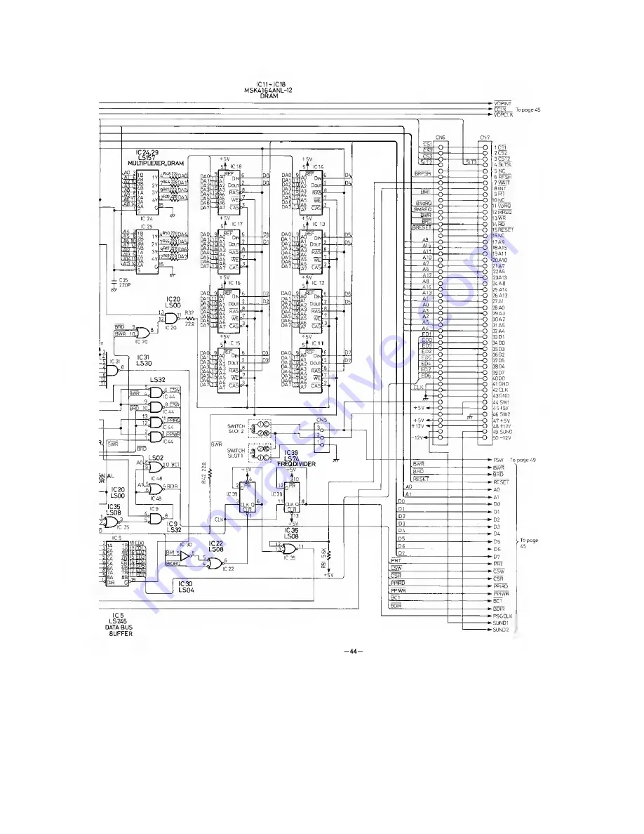
Страница 7: ...e gener ates CPU CLOCK in the circuit of 74LS74 IC42 and 74LS107 IC47 which divides VDP CLOCK by 3 to get 3 559384 MHz Moreover CLOCK Generator Circuit di vides CPU CLOCK into halves to get 1 779462 MHz by 74LS74 IC39 and gen erates PSG CLOCK CPU CLOCK 3 55938MH IIC8 PIN6I PSG CLOCK 1 77946 MHz I1C 39 PIN 8 Fig 2 CLOCK Waveform The Reset Circuit utilizes the charge of CR Circuit C13 and R26 but it...

Страница 8: ...erated by being staggered the time with the condenser C35 when the column address is outputted C35 ensures that the CAS will be L considering differences of the output timing of 74LS157 after the switchover of the row address to the column address WE is generated by BWR and OE by BRD RAS CAS WE and OE protect from the undershoot by being inserted a resist ance for the damping All of Input Output w...

Страница 9: ... Select signal and BWR BRD SWR Automatic refreshing function of VRAM Composite video output in PAL system Interruptible in every frame Automatic processing of the sprite screen This system uses TI s TMS9929A as CRTC This LSI s features are as follows 256 x 192 pixels resolution Used 4 8 and 16 KB as VRAM 16 KB is used in MSX Table 1 Screen Mode of VDP A VDP s operation depends on values of 9 READ ...

Страница 10: ...is occasion each bit in port A B is assigned as the following table 1 I O Function Input PORT 1 1 PORT 2 1 10 A1 PORT 1 2 PORT 2 2 10 A2 PORT 1 3 PORT 2 3 10 A3 PORT 1 4 PORT 2 4 10 A4 PORT 1 6 PORT 2 6 10 A5 PORT 1 7 PORT 2 7 10 A6 Input specifying the layout of Keyboard 10 A7 Read signal input from a cassette tape recorder 10 B0 Output P0RT1 10 Bl PORT1 10 B2 P0RT2 10 B3 P0RT2 10 B4 P0RT1 10 B5 ...

Страница 11: ...Slot Signal Generator Circuit CF 2700 adopts MODE 0 ports A C for output and port B for input This LSI is utilized for specifying the slot num ber controlling Keyboard for output to a cassette tape recorder and its control and output of click sound Bits of three ports are assigned as the following table Port I O Bit Function A 0 7 Specifying the Slot Number B 0 7 Keyboard Return Signal C Output 0 ...

Страница 12: ...umber of address bank in units of 16 KB Port A is preset for this operation as the following table Bit of Port A Contents PAl PAO Slot Number of Page 0 PA3 PA2 Slot Number of Page 1 PA5 PA4 Slot Number of Page 2 PA7 PA6 Slot Number of Page 3 Table 5 Meaning of each bit in Port A LS245 DATA BUS BUFFER Fig 11 Data Bus Buffer Circuit CS1 CS2 and CS12 are generated from A15 and A14 by decoder 74LS139 ...

Страница 13: ...0 A10 0 21 A7 0 22 A6 0 23 A12 0 24 A8 0 25 A14 0 26 A13 0 27 Al 0 28 AO 0 29 A3 0 30 A2 0 31 A5 0 32 A4 0 33 D1 I O 34 DO I O 35 D3 I O 36 D2 I O 37 D5 I O 38 D4 I O 39 D7 I O 40 D6 I O 41 GND 42 CLOCK 0 43 GND 44 SW1 _ 45 5 V 46 SW2 _ 47 5 V 48 12 V _ 49 SUNDIN I 50 12 V a Note 1 The distinction of Input Output is based on the mainframe b Reserved terminals are forbidden using Table 6 Connected ...

Страница 14: ...n of external Data Bus Select a cartridge and outputs L level from each cartridge except Memory at the same time when the data are outputted 11 IORQ I O Request Signal 12 MERQ Memory Request Signal 13 WR Write Timing Signal 14 RD Read Timing Signal 15 RESET System Reset Signal 16 RESERVED For furture use 17 32 A0 A15 Address Bus Signal 33 40 D h D7 Data Bus Signal 41 GND Ground 42 CLOCK CPU Clock ...

Страница 15: ...set for adjusting to the amplifier s character istic on the cassette This circuit has the gain by using OP Amp and also the characteristic as the filter the wave form characteristic at this time is as follows This circuit uses a high speed com parator to ensure the reproducing of 4800 Hz waveform The standard voltage supplied to the comparator is set to about 2 5 V by resistance division This volt...

Страница 16: ...ge output with resist ances R5 VR1 and R80 that is enables to vary an output voltage by adjusting a value of VR1 voltage dividing ratio The detection of errors between the reference and output voltages is made in a differential amplification circuit of transistors Q8 and Q2 This control method is as the following 5 V output voltage ascends 4 Base current of the transistor Q8 de creases 4 Current f...

Страница 17: ... is made by transistor Q9 and IC1 Pin No 4 in IC1 is a terminal of which output voltage becomes about 0 V when current more than about 500 yA flows If con trolled this pin externally it enables to control 12 V output voltage The 5 V output is to be 0 V with 12 V being 0 V because its reference voltage is made by divid ing 12 V as described in 1 The output voltage control by the Pin No 4 in IC1 is ...

Страница 18: ... settings on the TV for personal computer use are slightly different from that for TV broadcast reception Adjust according ly when switching from a TV broadcast to the personal computer Note 1 Character patterns are displayed as 8H x 6W dots character in the AO column text display mode SCREEN 0 8H x 8W dots cha racter in the 32 column text display mode For this reason the right side of some graphi...

Страница 19: ...the interpreter operates correctly 8 Screen display check Check if the screen displays correctly 9 Cassette I O check Check if signals are inputted outputted correctly 10 Joystick input check Check if the joystick sends its signals correctly by operating it 11 Print out check Check if the printer is sent the correct print out data 12 Audio output check Check if the audio sound is outputted properl...

Страница 20: ... 22 VRAM BUS line CPU VDP IBasic check on Printer Printer circuit terminals cables and printer ...

Страница 21: ...rints out If your printing output matches shown left it is OK 23 ...

Страница 22: ... 24 ...

Страница 23: ... 25 Foreground White Background Black Periphery Light Blue ...

Страница 24: ...It is OK if the screen display in the above turns over and s 32 by 24 are displayed 26 yellow blue light blue ...

Страница 25: ...It is OK if the screen display in the above turns over and E s 32 by 24 are displayed 27 ...

Страница 26: ...Depress fsFACEl Key CRT Screen Displays The overlapped 32 sprites are displayed 28 ...

Страница 27: ...After depressing the save Save Record button of the cassette tape recorder 29 ...

Страница 28: ... 30 ...

Страница 29: ... 31 NOISE 11 NOISE 21 NOISE 31 When the sound is outputted the corresponding indicator ...

Страница 30: ... 32 ...

Страница 31: ...RF MODULATOR Block Diagram 33 ...

Страница 32: ...tches B 3 1 3 Pull the Top Cabinet in the direction of arrow Note 1 When disconnecting the cable for the Micro Switches from the Connector CN5 remove it pressing the top of the Connector 2 When connecting the cable to the Connector CN5 make sure proper connection The lead coloured white must be connected to Pin 1 of the Connector Keyboard Fig 31 Fig 30 34 ...

Страница 33: ...Keyboard With the both sides of the reinforced portion being held connect disconnect them Main Board Cable for the keyboard Reinforced portion Connector CN8 CN9 CN1 Ref No Procedure Shown in Fig To remove Remove 7 1 7 Fig 32 Main Board Screw 3 x 10 A x 5 Screw 3 x 8 B x 1 8 1 3 8 Remove the Socket from the connector CN1 and CN2 9 1 9 Fig 33 Pull the Main Board in the direction of arrow Note When d...

Страница 34: ......

Страница 35: ... 3 x 8 A x 1 16 7 10 15 16 Fig 38 Power Source Board Remove the Socket from the Connector CN101 and CN102 17 7 11 15 17 Pull the Power Source Board in the direction of arrow Note When disconnecting the Socket from the Connector remove it Press with the latch being pressed CN101 37 ...

Страница 36: ...anel Unlatch the latches of the Slot Panel C x 4 21 1 3 18 21 Fig 40 Remove the Slot Panel in the direction of arrow J 22 1 3 18 22 Slot Cover Remove the Slot Cover in the direction of arrow 2 Note Care should be taken during disas sembly so as not to damage the slot panel When unlatching avoid applying excessive force to the latch for rupture Latch of the slot panel 38 ...

Страница 37: ...med precisely Connect the Spectrul Analyzer to RF output jack of the computer Then adjust the channel adjust trimmer as follows Channel Frequency MHz 35 583 25 36 591 25 37 599 25 Power Source Clock Frequency Adjust the VRl so that the DC voltage at Pin 45 of the connector CN7 is within 4 97 5 03 V DC Voltage Meter Connect the clips of the Frequency counter to the Pin 9 of IC203 on Video Board Adj...

Страница 38: ...LEFT I 4 RIGHT I 5 5 V Note 2 6 TRG 1 I O 7 TRG 2 I O 8 Output 0 9 GND Cassette I O Port DIN8 pin Signal Lines List Terminal Signal Number Name 1 GND 2 GND 3 GND 4 CMTOUT 5 CMTIN 6 REM 7 REM 8 GND Front view of the panel mounted connector Printer Port Amphenol 14 pin Signal level TTL level Signal Lines List 7 6 5 4 3 2 1 114 l3l 12 l l lo 9 1 8 Front view of the panel mounted connector Terminal Nu...

Страница 39: ...Note 4 Note 5 Note 6 Note 7 Input or output with respect to the computer System reserve terminal Be sure to input using an open collector output Load current 300 mA or less Load current 50 mA or less Load current 50 mA or less Be sure to fully understand the signals before actual designing a slot connected interface 41 ...

Страница 40: ...OTO AC SOCKET Wiring Connection Diagram b MICRO SWITCH z 3 3 C3 to C J CO CASSETTE PRINTER I O PORT PORT TRANSFORMER POWER ...

Страница 41: ...Schematic Diagram Main Board IC10 LS153 DATA SELECTOR IC23 IC 22 LSI39 LS08 DECOCER AND GATES BUFFER 43 ...

Страница 42: ...IC11 IC18 MSK4164ANL 12 DRAM VDPINT CCLK To page 45 VDPCLK 44 ...

Страница 43: ...Schematic Diagram Main Board 45 ...

Страница 44: ......

Страница 45: ...Printed Circuit Board Main Board MICRO SWITCH MICRO SWITCH SLOT 1 ...

Страница 46: ...jjjn i gp S mmMwmm IRW v l j 1 l i j wwwi rp y L ji TTToT ggj j vA wj Sfed J l7S 48 ...

Страница 47: ...Schematic Diagram Printed Circuit Board Po v r ourc Main Board ...

Страница 48: ...OR_ ENCODER BUFFER ADDER EMITTER FOLLOWER Schematic Diagram Video Board 50 Copyright 1983 by Microsoft 28815 Bytes free OK was displayed in the CRT screen When turning the computer on For waveform of sound the sound A was beeped by following programming 10 PLAY AAAAAAAAAA 20 GOTO 10 ...

Страница 49: ......

Страница 50: ......

Страница 51: ...8255AC 5 EXPLANATION OF TRUTH TABLES The following symbols are now being used in truth tables H L X z a h high level steady state low level steady state transition from low to high level transition from high to low level irrelevant any input including transitions off high impedance state of a 3 state output the level of steady state inputs at inputs A through H respectively level of Q before the i...

Страница 52: ...A t ni 48j 3Y r U 3 A g 3B 3Y OUTPUT Positive logic Y AB 3 DN74LS04 RVITC74HC04P Positive logic Y A 8 DIRECT COUPLING o _rii RESET INPUT L DATA INPUT ID Hi CLOCK INPUT IT S B son DIRECT COUPLING reset INPUT B 20 DATA INPUT 0 2T CLOCK INPUT 5 eT DIRECT COUPLING SET INPUT TRUTH TABLE INPUTS IKHE EIEII mraiaoi OIJ3HEHI ETJIICIUI This configuration is nonstable 54 ...

Страница 53: ... 55 ...

Страница 54: ... 13 DN74LS139 ...

Страница 55: ......

Страница 56: ... 19 DN74LS367A 21 AN6553 ...

Страница 57: ......

Страница 58: ......

Страница 59: ... J L DATA BUS 37l A7 V 36 A6 DATA BUS _ CONTROL INSTRUCTION OECOOE NTERNAl DATA BUS ALU 16 BIT ADDRESS BUS 32 UPD8255AC 5 GND C 7 Ai C 8 AOC9 pct c io PCsC II PCs C 12 PC C 13 PCoL 14 PCi C 15 PC 2 C 16 PCs C 17 PBo C 18 PBi C 19 PB2 020 40 PA4 39 PAs 37 DPAt 36 nWR DIRECTIONAL DATA BUS ...

Страница 60: ...i L QM Parts Location ...

Страница 61: ...Parts Location Keyboard 63 ...

Страница 62: ... 1015 DA4164ANL12M IC DYNAMIC RAM 1 IC16 DA4164ANL12M IC DYNAMIC RAM 1 IC17 DA4164ANL12M IC DYNAMIC RAM 1 IC18 DA4164ANL12M IC DYNAMIC RAM 1 IC19 DN74LS74A IC WRITE SIGNAL GENERATOR 1 Ref No Part No Part Name Description Per Set IC20 DN74LS00 IC QUADRUPLE NAND GATES 1 IC21 DN74LS125A IC RESET BUFFER 1 IC22 DN74LS08 IC QUADRUPLE AND GATES 1 IC23 DN74LS139 IC DECODER SLOT 1 IC24 DN74LS157 IC MULTIPL...

Страница 63: ...hms 1 R32 ERDS2TJ220 Registor 22 ohms 1 R33 ERDS2TJ562 Registor 5 6K ohms 1 R34 ERDS2TJ103 Registor 10K ohms 1 R35 ERDS2TJ562 Registor 5 6K ohms 1 R36 ERDS2TJ681 Registor 680 ohms 1 R37 ERDS2TJ563 Registor 56K ohms 1 R38 ERDS2TJ273 Registor 27K ohms 1 R39 ERDS2TJ220 Registor 22 ohms 1 R40 ERDS2TJ102 Registor IK ohms 1 R41 ERDS2TJ220 Registor 22 ohms 1 R42 ERDS2TJ220 Registor 22 ohms 1 R43 ERDS2TJ4...

Страница 64: ...IDER 1 IC204 DN74LS74A IC FREQUENCY DIVIDER 1 IC205 DN74LS86 IC QUADRUPLE OR GATES 1 Q201 2SB641Q Transistor 1 Q202 2SC2647B Transistor 1 Ref No Part No Part Name Description Per Set Q203 2SC2647B Transistor i Q204 2SB641Q Transistor i D201 MA165 Diode i D202 MA165 Diode i D203 MA165 Diode i D204 MA165 Diode i D205 MAI 65 Diode i X201 DECA08867H1M Crystal i L201 ELEMY390KA Coil i L202 ELEMY390KA C...

Страница 65: ... 48 DFWV70C0048 Key Button L 1 Ref No Part No Part Name Description Per Set 49 DFWV70C0049 Key Button 1 50 DFWV70C0050 Key Button 1 51 DFWV70C0051 Key Button 1 52 DFWV70C0052 Key Button 43 1 53 DFWV70C0053 Key Button O 1 54 DFWV70C0054 Key Button Z 1 55 DFWV70C0055 Key Button X 1 56 DFWV70C0056 Key Button C 1 57 DFWV70C0057 Key Button V 1 58 DFWV70C0058 Key Button B 1 59 DFWV70C0059 Key Button N 1...

Отзывы: