background image

7

22

23

25

24

OUT

IN

OUT

IN

S-VIDEO  

AFC

NORMAL

FAST

OUT

IN

SERVICE

CUT OFF

B

1

R

G

DRIVE

R

G

VIDEO A

OUT

IN

EXT SYNC

AUDIO

TALLY/
REMOTE

OUT

IN

VIDEO B

AC IN

DC IN

12V

2

2

1

THIS APPARATUS
MUST BE EARTHED

+

-

LINE B

LINE A

WARNING

< Rear Panel >

21

OUT

IN

AFC

NORMAL

FAST

TALLY/
REMOTE

To AC outlet
(120 V AC, 50 Hz/60 Hz)

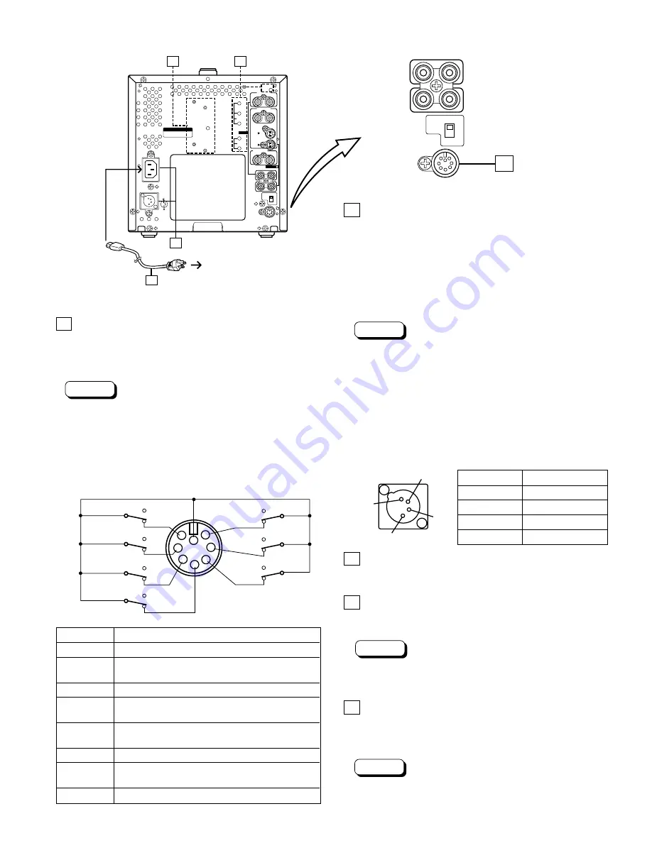
21 TALLY/REMOTE terminal

External control terminal (DIN 8-pin). Tally lamp, VIDEO
A/B (input selection), Under Scan, External Sync, 4:3/16:9
(aspect ratio), Pulse Cross, and Color Off modes can be
controlled from an external unit.

Note:

* When you’re controlling the monitor externally via the

TALLY/REMOTE terminal, set all corresponding
switches on the front panel to the OFF (

G

) position.

(Whichever switch is pressed first has priority so remote
switches may not function if the panel switches are ON
(

g

) position.)

 TALLY/REMOTE terminal pin layout

Pin No.

Signal

1

TALLY lamp

ON/OFF

2

LINE A/B

A/B

(Input Select)

3

UNDER SCAN

ON/OFF

4

EXT SYNC

ON/OFF

(External Sync)

5

4 : 3 /16 : 9

4 : 3 /16 : 9

(Aspect Ratio)

6

PULSE CROSS

ON/OFF

7

MONO
(color off)

ON/OFF

8

GND

22 Power input connector

Supply power to either the AC IN or DC IN 12 V
connector.

[AC IN]
Connect the provided AC power cord between the AC IN
connector and an AC outlet (120 V AC, 50 Hz/60 Hz).
[DC IN 12 V]
Connect the 12 V DC power plug to the DC IN 12 V
connector.

Notes:

* See your dealer for more information on 12 V DC power

supply.

* When both AC IN and DC IN connectors are used, the

AC input has priority.

* The DC power supply does not automatically take over

if an AC outlet is unplugged or the AC power is cut off
when both AC and DC power supplies are connected.
In this case, press the POWER switch to set to OFF,
then press it again to turn the power ON.

 DC IN 12 V connector pin layout

23 Power cord

Connect the provided power cord (120 V AC, 50 Hz/60 Hz)
to the AC IN connector.

24 External battery mounting holes

Attach an external battery to either pair of holes (1 or 2) to
use 12 V DC power (depending on the type of battery).

Notes:

* External batteries manufactured by Anton Bauer or PAG

are available.

* See your dealer for details.

25 Switch/control adjustment holes for service

personnel

For adjustment of SERVICE switch, CUT OFF (B, R, G)
control and DRIVE (R, G) control during servicing.

Note:

* These controls are exclusively for the use of service

personnel. Do not attempt to adjust them yourself.

1

3

2

4

  Pin No.                 Signal

1

GND

2

3

4

12 V DC

1

2

3

4

5

6

7

8

UNDER
SCAN

LINE (INPUT 
SELECT)


OFF


ON


B


A

4:3/16:9 
(ASPECT RATIO)


16:9


4:3

MONO

(color off)


OFF


ON

EXT
SYNC

TALLY

GND

PULSE
CROSS

OFF

ON

OFF

ON

OFF

ON

 LCT1182-001A-H (EN)Letter Size

02.3.15, 12:24 PM

Page 7

Adobe PageMaker 6.0J/PPC

Содержание BTS950 - COLOR VIDEO MONITOR

Страница 1: ...connect operate or adjust this product please read these instructions completely Printed in Thailand VQT9992 P LCT1182 001A H 0302 PN Y U JMT POWER UNDER SCAN PULSE CROSS MONO BLUE EXT SYNC LINE A LINE B NTSC PAL V HOLD NTSC PAL 4 3 16 9 CONTRAST BRIGHT CHROMA PHASE VOLUME S950 BT ...

Страница 2: ...s monitor There are no user serviceable parts inside Unplug the monitor when you re not going to be using it for a long period 䡵 HANDLING Avoid shocks or vibrations These may damage the unit and cause it to malfunction Do not block the ventilation slots Do not expose this unit to high temperatures Extended exposure to direct sunlight or a heater could deform the cabinet or cause the performance of...

Страница 3: ...3 CONTENTS SAFETY PRECAUTIONS 2 CONTROLS AND FEATURES 4 BASIC CONNECTION EXAMPLE 8 TROUBLESHOOTING 9 SPECIFICATIONS 10 ...

Страница 4: ... to suit the NTSC or PAL color system 6 LINE A B switch Select the video signal input to the video input terminals on the rear panel A G Selects the video signal input to LINE A terminal B g Selects the video signal input to LINE B terminal Note LINE B terminals include both S VIDEO Y C and composite VIDEO terminals S VIDEO inputs have priority 7 EXT SYNC switch Selects internal sync or external s...

Страница 5: ...a and phase adjustment G Normal screen g Monochrome blue screen Note The PHASE adjustment is effective only in the NTSC color system mode How to adjust 1 Select the monochrome blue screen mode and input color bar signals in the order of brightness 2 Adjust the CHROMA and PHASE controls until the density and brightness of each blue bar are the same 3 4 5 6 11 12 13 14 7 8 9 10 POWER UNDER SCAN PULS...

Страница 6: ...1 19 18 17 16 15 OUT IN OUT IN S VIDEO AFC NORMAL FAST OUT IN VIDEO A OUT IN EXT SYNC AUDIO TALLY REMOTE OUT IN VIDEO B LINE B LINE A To AC outlet 120 V AC 50 Hz 60 Hz Pin No Signal 1 GND Y 2 GND C 3 Y 4 C 17 EXT SYNC terminals External sync signal input IN and output OUT terminals The output terminal is bridge connected IN Input terminal for the external sync signal OUT Bridge connected output te...

Страница 7: ...d between the AC IN connector and an AC outlet 120 V AC 50 Hz 60 Hz DC IN 12 V Connect the 12 V DC power plug to the DC IN 12 V connector Notes See your dealer for more information on 12 V DC power supply When both AC IN and DC IN connectors are used the AC input has priority The DC power supply does not automatically take over if an AC outlet is unplugged or the AC power is cut off when both AC a...

Страница 8: ...you re not connecting any equipment to a bridged output OUT terminal be sure not to connect any other cables to the bridged output OUT terminal as this will cause the terminating resistance switch to open auto terminate function When making a bridge connection connect the input IN and output OUT terminals on the monitor to separate video components For example if both terminals are connected to th...

Страница 9: ...he OFF G position See pages 4 5 7 and 8 Points to be checked Is the AC or DC power plug loosened or disconnected Is the battery fully charged when using DC power Is the video signal output from the connected component Is the input signal selected properly Is the video cable disconnected Is the audio signal output from the connected component Is the volume output set at the minimum position Is the ...

Страница 10: ...nation S VIDEO priority when both connected AUDIO A 1 line monaural RCA pin x 2 0 5 V rms high impedance bridge connection possible AUDIO B 1 line monaural RCA pin x 2 0 5 Vrms high impedance bridge connection possible 7 External sync Composite sync 1 line BNC connector x 2 1 4 Vp p 75 Ω bridge connection possible auto termination 7 Tally Remote 1 line DIN 8 pin x 1 7 Audio power output 1 W monaur...

Страница 11: ...ROSS MONO BLUE EXT SYNC LINE A LINE B NTSC PAL V HOLD NTSC PAL 4 3 16 9 CONTRAST BRIGHT CHROMA PHASE VOLUME S950 S950 BT 䡵 Dimensions Unit inch mm Asterisks are used to indicate front panel dimensions Front View Side View 12 1 2 317 8 3 4 222 2 1 2 63 5 1 16 1 5 12 1 8 305 3 8 7 3 8 7 ...

Страница 12: ...68 323 436 3500 Government Marketing Department 52 West Gude Drive Rockville MD 20850 301 738 3840 Broadcast PARTS INFORMATION ORDERING 9 00 a m 5 00 p m EST 800 334 4881 24 Hr Fax 800 334 4880 Emergency after hour parts orders 800 334 4881 TECHNICAL SUPPORT Emergency 24 Hour Service 800 222 0741 Panasonic Canada Inc 5770 Ambler Drive Mississauga Ontario L4W 2T3 905 624 5010 Panasonic de Mexico S ...

Отзывы: