background image

14

Power Supply

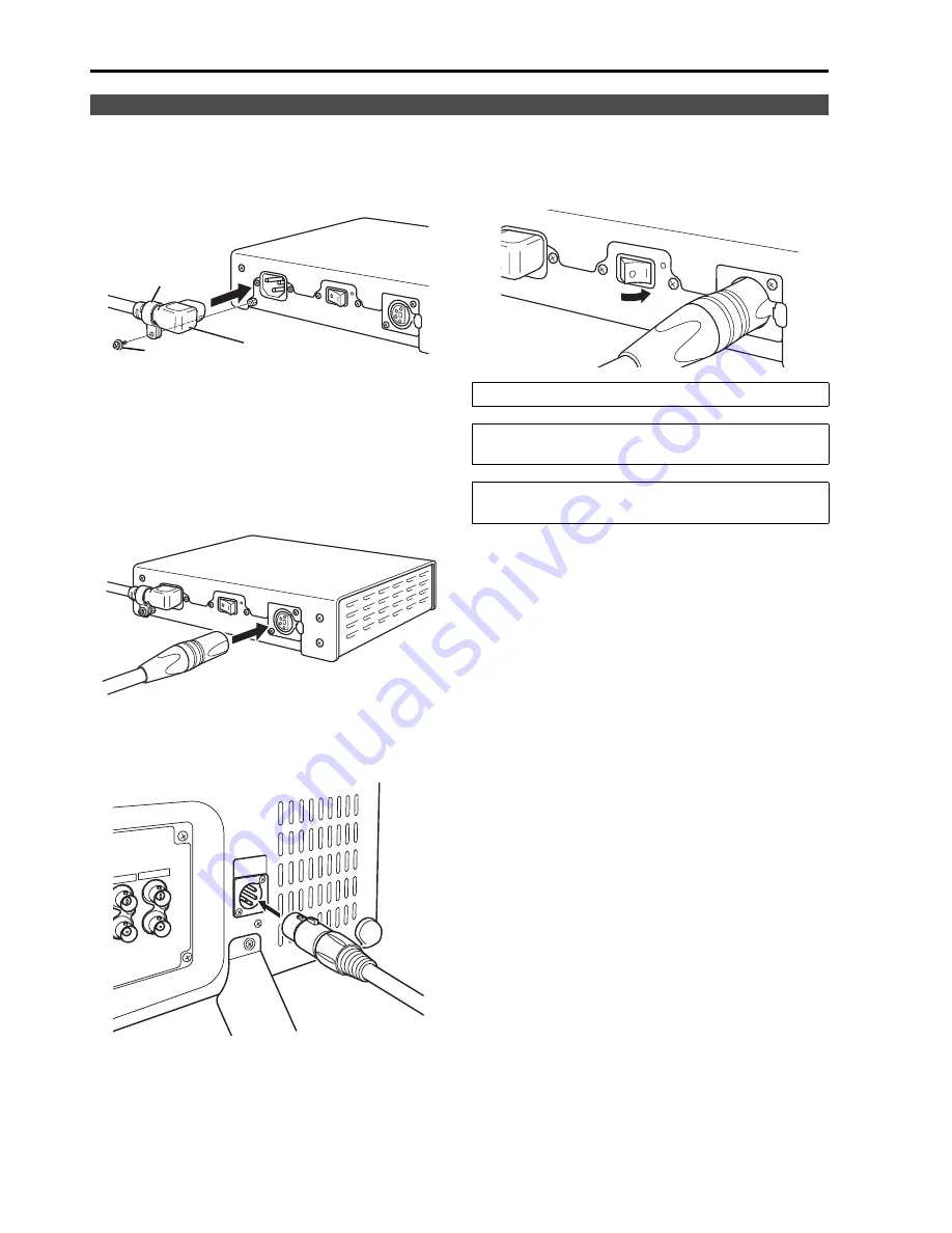
1. Connect the power cord to the AC inlet of the AC

adapter.

Use the supplied screw (for securing power cord)
and the power cord hook to secure the power cord to
the AC adapter.

2. Slide the supplied DC cord into the DC OUT

terminal on the AC adapter until it is locked in
place.

3. Slide the DC cord into the DC IN terminal on the

unit until it locks in place.

4. Connect the power cord to an AC outlet.

5. Turn on the POWER switch. The POWER LED

lights green. 

Connecting the power cord

Power cord hook

Screw

Power cord

Be sure to use the supplied AC adapter.

Do not use the supplied AC adapter for powering
other devices.

The AC adapter generates heat during use, which is
normal and not a cause for concern. 

Содержание BT-LH2550

Страница 1: ...the instructions carefully and save this manual for future use DEUTSCH Für Erlauterungen in Deutsch konsultieren Sie bitte die mitgelieferte CD ROM FRANÇAIS Pour des explications en français veuillez vous reporter au CD ROM fourni ITALIANO Per le istruzioni in italiano vedere il CD ROM in dotazione ESPAÑOL Para la explicación en español consulte el CD ROM uministrado ...

Страница 2: ...ace To prevent risk of electric shock or fire hazard due to overheating ensure that curtains and any other materials do not obstruct the ventilation CAUTION TO REDUCE THE RISK OF FIRE OR SHOCK HAZARD AND ANNOYING INTERFERENCE USE THE RECOMMENDED ACCESSORIES ONLY CAUTION This apparatus can be operated at a voltage in the range of 100 240 VAC Voltages other than 120 V are not intended for U S A and ...

Страница 3: ...ucus NJ07094 Support contact Panasonic Broadcast Television Systems Company 1 800 524 1448 This device complies with Part 15 of FCC Rules Operation is subject to the following two conditions 1 This device may not cause harmful interference and 2 this device must accept any interference received including interference that may cause undesired operation To assure continued compliance follow the atta...

Страница 4: ...REDUCE THE RISK OF FIRE OR SHOCK HAZARD KEEP THIS EQUIPMENT AWAY FROM ALL LIQUIDS USE AND STORE ONLY IN LOCATIONS WHICH ARE NOT EXPOSED TO THE RISK OF DRIPPING OR SPLASHING LIQUIDS AND DO NOT PLACE ANY LIQUID CONTAINERS ON TOP OF THE EQUIPMENT CAUTION TO REDUCE THE RISK OF FIRE OR SHOCK HAZARD AND ANNOYING INTERFERENCE USE THE RECOMMENDED ACCESSORIES ONLY CAUTION In order to maintain adequate vent...

Страница 5: ...ng of 13 amps and that it is approved by ASTA or BSI to BS1362 Check for the ASTA mark or the BSI mark on the body of the fuse If the plug contains a removable fuse cover you must ensure that it is refitted when the fuse is replaced If you lose the fuse cover the plug must not be used until a replacement cover is obtained A replacement fuse cover can be purchased from your local Panasonic Dealer C...

Страница 6: ...EBU Use shielded cables which provide quality performance for high frequency transmission applications for analog audio signals Other connecting cables IEEE1394 USB Use shielded cables which provide quality performance for high frequency applications as connecting cables When connecting to the DVI signal terminal use a cable with a ferrite core If your apparatus is supplied with ferrite core s the...

Страница 7: ...LCD screen to intense light sources will impair its characteristics and lower image quality In an environment exposed to drastic temperature fluctuations condensation may build up on and inside the LCD screen This may lower the quality of the screen and may damage it Some video images may appear blurred on the screen Leaving the unit in a location exposed to high temperature and humidity for an ex...

Страница 8: ...on without blurring The gamma correction of each monitor is set individually prior to shipment Multi format image compatibility This monitor is equipped with SDI HD SD compatible VIDEO YPBPR RGB DVI D HDCP compatible input jacks It supports both NTSC and PAL TV broadcast systems A host of functions Split screen function You can display two selected inputs in two windows and set a separate color sp...

Страница 9: ...3 30 1 2 410 16 1 599 23 6 343 8 13 5 550 08 21 7 When installing the monitor in one place permanently we recommend that you fix the monitor in place using the screw holes in the lower part of the stand Unit mm inches 46 1 8 64 2 5 73 5 2 9 48 5 1 9 150 5 9 200 7 9 232 9 1 4 5 0 2 46 1 8 177 7 0 Unit mm inches The rating plate is on the underside of the AC Adapter Dimensions ...

Страница 10: ...ed at the bottom of the front panel This switch turns the power On and Off Set the switch to to turn it on Power LED When the power is turned on the LED lights green DC IN Connect the supplied DC cord of the supplied AC adapter to this terminal Rear panel terminals page 12 Video monitor unit 6 5 Front view Rear view Controls and Their Functions ...

Страница 11: ...the cursor to the left Use to select the picture volume adjusting menu or to confirm a menu item assigned to the FUNCTION1 FUNCTION2 Moves the cursor to the right Use to select the picture volume adjusting menu or to confirm a menu item assigned to the FUNCTION2 FUNCTION3 Moves the cursor downwards Use to select the picture volume adjusting menu or to confirm a menu item assigned to the FUNCTION3 ...

Страница 12: ...als OUT This is the input signal through out terminal When using RGB signals from a PC connect the horizontal synchronizing signal to the SYNC HD terminal and the vertical synchronizing signal to the VD terminal GPI input terminal D SUB 9 pin External control is possible by using a GPI signal RS232C terminal D SUB 9 pin External control is possible by using an RS232 signal HEADPHONES output connec...

Страница 13: ... ON OFF This switch turns the AC adapter on and off POWER lamp This lamp lights green when the POWER switch is set to on DC OUT This is the DC output terminal This terminal enables connection of a DC cord AC Adapter 2 3 4 1 Controls and Their Functions continued ...

Страница 14: ...adapter until it is locked in place 3 Slide the DC cord into the DC IN terminal on the unit until it locks in place 4 Connect the power cord to an AC outlet 5 Turn on the POWER switch The POWER LED lights green Connecting the power cord Power cord hook Screw Power cord Be sure to use the supplied AC adapter Do not use the supplied AC adapter for powering other devices The AC adapter generates heat...

Страница 15: ...ious indications FILM mode This indicates that GAMMA SELECT is set to FILM in the VIDEO CONFIG menu 4 Signal format Use STATUS DISPLAY in the SYSTEM CONFIG menu to set the display status page 29 UNSUPPORT SIGNAL appears if an unsupported signal is input It may also indicate that the format selected in the INPUT SELECT menu does not match the input signal NO SIGNAL appears if no signal is input Not...

Страница 16: ... switch the level display on off and set the number of displayed channels using the menu page 38 AUDIO The 0 dB line and channel display can be switched on off from the menu page 38 AUDIO This is the menu display It disappears after 2 minutes of inaction You can change position of the display page 29 MENU POSITION FUNCTION display F1 MARKER F2 WFM VECTOR F3 TWO WINDOW F4 TIME CODE F5 LEVEL METER X...

Страница 17: ...roup The delimiter does not appear Note Read errors are displayed as Display position and character size can be modified page 39 POSITION and FONT SIZE in the DISPLAY SETUP menu Use the menu to display and set closed caption display for VIDEO NTSC signals It also allows you to select display mode CC1 to CC4 page 39 CLOSED CAPTION and MODE SELECT in the DISPLAY SETUP menu Note Closed captions are n...

Страница 18: ...ER 3 Press to select a sub menu and press ENTER The settings in the sub menu change to green 4 Press to select a setting then press ENTER To cancel press MENU To return to the previous screen Press the MENU button Menu operations MAIN MENU How to Use the On Screen Menu continued ...

Страница 19: ...ions When CONTROL in the CONTROL menu is set to REMOTE the key mark appears and adjustments cannot be changed Setting the MONO function to ON page 27 disables the PHASE and CHROMA operations During RGB COMP and DVI COMP input the PHASE and CHROMA operations are disabled During HV DELAY page 33 operation and a setting other than OFF is selected BRIGHT operation is disabled 4 Press ADJUST to end adj...

Страница 20: ...pears 5 Select YES and press ENTER This saves the user data 1 Press MENU to display the MAIN menu 2 Press to select the SYSTEM CONFIG menu and press ENTER 3 Press to select the SETUP LOAD sub menu and press ENTER The setting in the sub menu changes to green 4 Press to select a USER1 to USER5 file to load and press ENTER The following screen appears To return to the factory defaults select FACTORY ...

Страница 21: ...RESET AUDIO INPUT SELECT EMBEDDED SELECT L EMBEDDED SELECT R LEVEL METER CH SELECT 0 dB POINT CH INFO MARKER 16 9 4 3 BACK CENTER GPI PRESET1 GPI PRESET2 MARKER TYPE CROSS HATCH FUNCTION1 FUNCTION2 FUNCTION3 FUNCTION4 FUNCTION5 FUNCTION DISPLAY COLOR TEMP GAIN RED GAIN GREEN GAIN BLUE BIAS RED BIAS GREEN BIAS BLUE RESET COLOR TEMP GAIN RED GAIN GREEN GAIN BLUE BIAS RED BIAS GREEN BIAS BLUE RESET C...

Страница 22: ...93 93 1 area marker TYPE1 93 area marker TYPE2 88 89 5 area marker TYPE1 88 area marker TYPE2 USER This area marker can be varied in 1 increments in the range between 80 to 95 However an 88 value for a TYPE1 MARKER TYPE indicates an area marker whose height is 89 of available screen height in the selected aspect ratio The factory default is 85 4 3 2 4 OFF 95 93 90 88 80 USER 85 Selects displays th...

Страница 23: ... for 16 9 aspect ratio 93 16 9 93 area marker for 16 9 aspect ratio 90 16 9 90 area marker for 16 9 aspect ratio 88 16 9 88 area marker for 16 9 aspect ratio 80 16 9 80 area marker for 16 9 aspect ratio 95 4 3 95 area marker for 4 3 aspect ratio 93 4 3 93 area marker for 4 3 aspect ratio 90 4 3 90 area marker for 4 3 aspect ratio 88 4 3 88 area marker for 4 3 aspect ratio 80 4 3 80 area marker for...

Страница 24: ...6 9 marker simultaneously Simultaneous display example The section becomes the MARKER BACK It controls the background of the marker selected with a 16 9 ratio Center marker Marker types 4 3 marker 13 9 marker 14 9 marker VISTA marker CNSCO marker VISTA marker CNSCO marker 95 Area marker 93 Area marker 90 Area marker 88 Area marker 80 Area marker USER area marker 1 TYPE1 Vertical 93 1 horizontal 93...

Страница 25: ...are spaced 120 dots apart fixed value Each press of the button FUNCTION1 to FUNCTION5 to which the CROSS HATCH has been assigned turns the function on and off Each press of the FUNCTION button to which the CROSS HATCH function is assigned changes the display as shown HD SD 16 9 mode SD 4 3 mode 1st press 2nd press Light cross hatch Dense cross hatch 3rd press back to original image without cross h...

Страница 26: ...creen when FILM is selected COLOR SPACE SMPTE C 7 EBU 7 ITU 709 WIDE1 WIDE2 WIDE3 Sets the color space The color space in the sub window can be set in the split screen display and sub window display single screen of the TWO WINDOW function SMPTE C SMPTE C standard EBU EBU standard ITU 709 ITU R BT 709 standard WIDE1 Sets the gamma curve to 2 2 in wide color gamut using Adobe color space mode WIDE2...

Страница 27: ... enlarged signal can be vertically compressed and corrected for display This function is not available in the split screen display of the TWO WINDOW function SD ASPECT 2 4 3 16 9 Sets the aspect ratio for SD signal input This function is not available in the split screen display of the TWO WINDOW function 4 3 4 3 display 16 9 16 9 display SCAN 2 NORMAL UNDER Sets under scan and normal display This...

Страница 28: ... adjustment USER 0 63 Adjustable settings 0 63 equivalent to a color temperature range of 3 000 9 300K D93 Equivalent to a color temperature of 9 300K D65 Equivalent to a color temperature of 6 500K D56 Equivalent to a color temperature of 5 600K USER20 is approximately 5000 K and USER33 is approximately 6300 K GAIN RED 0 1023 Factory defaults are color temperature D65 values These are the adjustm...

Страница 29: ...SER3 1 2 USER2 1 2 USER1 1 2 FACTORY Loads saved factory defaults FACTORY or user data USER1 USER5 After loading user data the screen displays the signal selected before user data was loaded SETUP SAVE USER5 2 USER4 2 USER3 2 USER2 2 USER1 2 Up to 5 sets of user data can be saved page 20 They save menu settings and adjustments made in the picture volume adjusting menu PHASE CHROMA BRIGHT CONTRAST ...

Страница 30: ...rocedures refer to the CA 210 User s Guide Turn on this unit and perform adequate aging about 1 hour before starting calibration Turn off the lights in the room and make sure that no external light can enter the standard measurement probe before starting the calibration External light that enters the probe will prevent correct calibration of low brightness characteristics LCD panel characteristics...

Страница 31: ...complete Check RS 232C cable connection 1 Press in the SYSTEM CONFIG menu select the CALIBRATION submenu and press ENTER 2 Press select the RESET submenu and press ENTER 3 Select YES and press ENTER This starts calibration xxxxxxxxx indicates that the following message with the meaning listed below appears COMPLETE Operation completed Sub menu Setting Description AUTO CALIBRATION 1 Connect a CA 21...

Страница 32: ...the following order EBU ITU 709 WIDE1 WIDE2 WIDE3 SMPTE C EBU SD ASPECT Switches between 16 9 and 4 3 1 SCAN Switches between UNDER SCAN and NORMAL SCAN 1 TWO WINDOW Sets the split screen function 1 The display changes in the following order When the input signal terminals of video displayed in the sub window and main window differ SINGLE MAIN TWO L S M M S L SINGLE SUB SINGLE MAIN When video from...

Страница 33: ...BPR RGB or DVI COMP is selected under DVI D in the INPUT SELECT menu the display toggles between single screen display of the main window and sub window When WINDOW SIZE is something other than M M the SINGLE MAIN and SINGLE SUB screens appear alternately but no still image screen appears When the input signal terminals of video displayed in the main window and sub window differ the SINGLE MAIN an...

Страница 34: ...SINGLE MAIN TWO L S TWO M M TWO S L STILL SINGLE SUB SUB INPUT SEL VIDEO SDI1 SDI2 YPBPR RGB DVI D WFM VECTOR WFM ON WFM VECTOR OFF VECTOR 1 VECTOR 2 VECTOR 4 VECTOR 8 MARKER MARKER OFF 4 3 MARKER 13 9 MARKER 14 9 MARKER VISTA MARKER CNSCO MARKER 95 MARKER 93 MARKER 90 MARKER 88 MARKER 80 MARKER MARKER indicates an 80 to 95 USER setting MARKER ON AUDIO LEVEL METER METER OFF METER 2CH METER 4CH MET...

Страница 35: ...ng other than RGB VIDEO is selected under YPBPR RGB in the INPUT SELECT menu MONO operation when input signal is PC GPI Sub menu Settings Description GPI CONTROL DISABLE ENABLE Enables and disables GPI functions DISABLE Disabled ENABLE Enabled GPI1 GPI8 UNDEF MARKER1 ON OFF MARKER2 ON OFF MARKER BACK HALF MARKER BACK BLACK CENTER MARKER INPUT SEL VIDEO INPUT SEL SDI1 INPUT SEL SDI2 INPUT SEL YPBPR...

Страница 36: ...DI2 line to the INPUT button on off 1 YPBPR RGB OFF ON Turns YPBPR RGB line to the INPUT button on off 1 MODE YPBPR RGB VIDEO RGB COMP Selects YPBPR component or RGB input mode YPBPR Selects the YPBPR signal RGB VIDEO Selects the video RGB signal RGB COMP Selects the PC RGB signal COMPONENT LEVEL SMPTE B75 B00 Selects YPBPR component signal input level SMPTE Signal level complies with SMPTE and PB...

Страница 37: ...t formats Selecting this submenu opens a confirmation screen and setup starts after choosing YES in this screen H POSITION 0 30 60 Adjusts horizontal image display position 2 V POSITION 0 30 60 Adjusts vertical image display position 2 PHASE 0 16 60 Adjusts the clock phase in 1 32 clock period increments 2 CLOCK 700 2200 Factory preset settings 3 Adjusts the sampling clock in dot units 2 WXGA XGA ...

Страница 38: ...ines other than SDI1 or SDI2 are selected with the INPUT button on the front panel analog AUDIO input terminal ANALOG Analog AUDIO input terminal EMBEDDED SELECT L CH1 CH8 Factory default CH1 Selects embedded audio channel output to the left L speaker EMBEDDED SELECT R CH1 CH8 Factory default CH2 Selects embedded audio channel output to the right R speaker LEVEL METER 1 OFF ON Selects turns off th...

Страница 39: ...OR waveform display 3 LB Left Bottom RB Right Bottom RT Right Top LT Left Top VECTOR MODE 8 4 2 1 Enlarges vector waveforms 3 8 8 4 4 2 2 1 1 VECTOR SCALE 100 75 Determines the scale of vector waveform 100 Displays it at 100 scale 75 Displays it at 75 scale TIME CODE OFF ON Turns the time code display on and off 1 POSITION TOP LEFT CENTER RIGHT Selects position of time code display TOP Top center ...

Страница 40: ...R function has been assigned to turn the function on and off This assumes that the WFM VECTOR function has been assigned to any of the FUNCTION1 to FUNCTION5 buttons These examples show 16 9 aspect ratio images 1 Displayed only for SDI signal input Normal screen WFM display VECTOR display 1 WFM waveform display VECTOR vector display Press the FUNCTION button to which the WFM VECTOR function has be...

Страница 41: ... for the main window and sub window both windows will show the same screen Main window normal window Video Main window Sub window Video Video Main window Sub window Still image Video Sub window Video Press the button again Press the button again Press the button again Press the button again Press the FUNCTION button to which the TWO WINDOW function has been assigned Main window Displays input sele...

Страница 42: ... Main window SD and sub window SD Main window HD and sub window HD 1920 1280 640 1280 640 960 960 TWO WINDOW SIZE setting L S Display size 4 3 or 5 4 TWO WINDOW SIZE setting M M TWO WINDOW SIZE setting S L 1920 1280 640 1280 640 960 960 TWO WINDOW SIZE setting L S Display size 16 9 or 16 10 TWO WINDOW SIZE setting M M TWO WINDOW SIZE setting S L ...

Страница 43: ...1920 1280 640 1280 640 960 960 TWO WINDOW SIZE setting L S Display size of main window 16 9 or 16 10 Display size of sub window 4 3 or 5 4 TWO WINDOW SIZE setting M M TWO WINDOW SIZE setting S L 1920 1280 640 1280 640 960 960 TWO WINDOW SIZE setting L S Display size of main window 4 3 or 5 4 Display size of sub window 16 9 or 16 10 TWO WINDOW SIZE setting M M TWO WINDOW SIZE setting S L ...

Страница 44: ...hat is not synchronized to the reference sync TWO WINDOW SIZE Sub window Input signal format Main window Input signal format 1035i 1080i 1080 24PsF 1080p 720p NTSC PAL 480i p 576i p DVI COMP No input or incompatible format L S 1035i 1080i 1080 24PsF Main window sync Split screen display Main window sync Single screen display 1080p 720p NTSC PAL 480i p 576i p DVI COMP No input or incompatible forma...

Страница 45: ...s XXXXXX 300000 hours or greater is displayed as OVER CONTROL Sub menu Settings Description CONTROL LOCAL REMOTE Selects operation with control clock LOCAL Enables front panel operation REMOTE Enables remote operation front panel operation is locked 1 LOCAL ENABLE 2 DISABLE INPUT Selects the disabled operation on the front panel when selecting REMOTE under CONTROL DISABLE Disables all front panel ...

Страница 46: ...n display of the TWO WINDOW function Input CH VIDEO SDI 1 2 YPBPR RGB VIDEO RGB COMP DVI VIDEO DVI COMP CH SD HD SD HD SD HD SD HD MARKER MARKER 1 16 9 1 4 3 1 BACK 1 CENTER 1 GPI PRESET1 1 GPI PRESET2 1 MARKER TYPE 1 CROSS HATCH 2 VIDEO CONFIG GAMMA SELECT 3 COLOR SPACE 3 COLOR TEMP 4 SHARPNESS MODE 4 SHARPNESS H 4 SHARPNESS V 4 I P MODE 4 MONO 4 ANAMO 1 SD ASPECT 1 SCAN 1 COLOR GAIN R 3 COLOR GA...

Страница 47: ... during SDI input Input CH VIDEO SDI 1 2 YPBPR RGB VIDEO RGB COMP DVI VIDEO DVI COMP CH SD HD SD HD SD HD SD HD DISPLAY SETUP 2 TWO WINDOW SIZE SUB INPUT SEL WFM VECTOR 5 5 5 POSITION VECTOR MODE VECTOR SCALE TIME CODE POSITION FONT SIZE MODE SELECT CLOSED CAPTION CAPTION SELECT Picture adjustment 2 PHASE CHROMA BRIGHT CONTRAST BACKLIGHT ...

Страница 48: ...ircuited ON Open OFF MARKER BACK BLACK 2 Reduces the brightness of the background outside the marker displayed in GPI PRESET1 page 23 to 0 Level operation Short circuited ON Open OFF CENTER MARKER Turns the center marker display on and off When other markers are displayed this marker is superimposed on other markers Level operation Short circuited ON Open OFF INPUT SEL VIDEO Switches the input lin...

Страница 49: ...gement and connections For details on systems using RS 232C be sure to consult your dealer Connectors and signals Connector D SUB 9 pin female Signal Communication parameters Command format The command is the 3 character string starting with STX and ending with ETX Append any data after the colon following the command as required Response formats 1 Setting command response 2 Query command response...

Страница 50: ...OFF 2 OFF DSD 8 ISM 2 Analog mode ANA0 YPBPR ANA1 RGB VIDEO ANA2 RGB COMP ISM 9 IRF 2 SELECT Sync 0 INT 1 EXT IRF 10 ISM 2 DVI D mode DVI0 DVI VIDEO DVI1 DVI COMP ISM 11 DMK 3 Marker settings 16 9 marker MK100 OFF MK101 80 MK102 88 MK103 93 MK104 95 MK105 14 9 MK106 13 9 MK107 4 3 MK108 90 MK109 CNSCO MK110 VISTA MK111 USER 4 3 marker MK200 OFF MK201 80 MK202 88 MK203 93 MK204 95 MK208 90 MK211 US...

Страница 51: ...D93 03 VAR1 04 VAR2 05 VAR3 10 73 USER0 63 9 QPC Sharpness SHP Sharpness mode 0 LOW 1 HIGH SHH Horizontal sharpness value 00 30 SHV Vertical sharpness value 00 30 10 QIP IP mode 0 MODE1 1 MODE2 11 QMO Monochrome 1 OFF 2 ON 12 QAS Aspect 0 16 9 1 4 3 13 QSC Scan 0 NORMAL 1 UNDER 14 QAN Analog mode 0 YPBPR 1 RGB VIDEO 2 RGB COMP 15 QSY SELECT sync 0 INT 1 EXT 16 QDV DVI D mode 0 DVI VIDEO 1 DVI COMP...

Страница 52: ...consumables Maintenance Clean the cabinet and protection panel by gently wiping it with a soft cloth To remove stubborn soiling use a cloth dampened in a weak neutral detergent solution and thoroughly wrung out Then wipe with a dry cloth Any moisture entering the monitor could damage it Do not use benzene thinner and similar solvents for cleaning They could discolor the surface and cause the paint...

Страница 53: ...S single link Vertical frequency 50 0 60 0 Hz Horizontal frequency 31 5 67 5 kHz Dot clock 25 to 165 MHz AUDIO input terminals Pin jack 2 stereo Signal level 0 5 Vrms DC IN terminals XLR 4 pins 1 Output VIDEO output terminals BNC 1 Through out Automatic 75 Ω termination SDI output terminals BNC 1 switched out YPBPR RGB output terminals BNC 3 Through out Automatic 75 Ω termination SYNC HD output te...

Страница 54: ...mensions when shown are approximately Specifications are subject to change without notice Input signal formats VIDEO SDI1 SDI2 YPBPR RGB VIDEO RGB COMP DVI VIDEO DVI COMP NTSC PAL 480 59 94i 480 59 94p 576 50i 576 50p 720 50p 720 59 94p 720 60p 1035 59 94i 1 1 1 1 1035 60i 2 2 2 2 1080 23 98PsF 1080 24PsF 1080 23 98p 1080 24p 1080 25p 1080 29 97p 1080 30p 1080 50i 1080 50p 1080 59 94i 1080 60i 108...

Страница 55: ...55 MEMO ...

Страница 56: ...utschland Tel 49 611 235 481 Panasonic Systems Asia Pacific Broadcast Regional Operation Center 2 Jalan Kilang Barat Panasonic Building Singapore 159346 Tel 65 6270 0110 Panasonic Corporation 2008 Information on Disposal for Users of Waste Electrical Electronic Equipment private households This symbol on the products and or accompanying documents means that used electrical and electronic products ...

Отзывы: