background image

AV6 (CS) Switches

Panasonic Corporation Electromechanical Control Business Division

industrial.panasonic.com/ac/e/

AECTB60E   202110

Panasonic Corporation 2021

GUIDELINES FOR USAGE

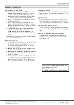
Fastening of the switch body

1)  To secure the switch, please use an M2.3 screw on a flat 

surface and tighten using a maximum torque of 0.29 N·m. 

It is recommended that both flat metal washer and spring 

washers be used with the screws and adhesive be applied 
to lock the screws to prevent loosening of the screws.

2)  Be sure to maintain adequate insulating clearance between 

each terminal and ground.

3)  When the operation object is in the free position, force 

should not be applied directly to the actuator or pin plunger. 
Also force should be applied to the pin plunger from vertical 
direction to the switch.

4)  In setting the movement after operation, the over-travel 

should be set more than 70% as a standard. 
With the lever type, do not apply excessive force in the 
direction opposite to the movement, or from the horizontal 
direction.

5)  After installing, attach with the lever side oriented downward 

to avoid the weight of the lever.

About the connector

1)  The connector on the AV6 (CS) switch is designed to fit with 

the XA connector produced by JST Mfg. Co., Ltd. Do not 

use any connector other than the specified connector, or 

solder the terminals directly.

2)  Make sure leads are arranged so that no constant force is 

applied to them when the connectors are mated.

3)  Keep the connector straight when inserting it. If it is inserted 

at an angle, it may snag near the entrance, or it may be 
inserted too forcefully.

4)  Problems thought to be caused by the XA connector, which 

is specified as conforming to the AV6 (CS) switch connector, 

are not covered by the warranty. Please contact JST Mfg., 
Co., Ltd. and request cooperation in resolving the problem.

Selection of switch

Please make your selection so that there will be no problems 
even if the operating characteristics vary up to ±20% from the 
standard values.

Environment

Avoid using and storing these switches in a location where 
they will be exposed to corrosive gases, silicon, or high dust 

levels, all of which can have an adverse effect on the contacts.

Precautions concerning circuits

The AV6 (CS) switch is designed specifically for low-voltage, 

low-current loads. Avoid using it at loads that exceed the rating 
load.

Quality check under actual loading conditions

To assure reliability, check the switch under actual loading 

conditions. Avoid any situation that may adversely affect 

switching performance.

Please refer to 

"the latest product specifications"

when designing your product.
•Requests to customers:

https://industrial.panasonic.com/ac/e/salespolicies/

ー 7 ー

Содержание AV620264

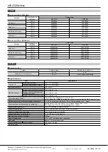
Страница 1: ...ying machine Printer Also for all types of equipment required for maintenance and inspections Unit mm 29 2 10 7 ORDERING INFORMATION PART NO AV 6 64 Operating Force OP by pin plunger Max 2 0 50 N 5 1 50 N Contact material 64 CuNi alloy Au clad contact Contact form 2 SPST NC Plunger color Red 3 SPST NO Plunger color Yellow Lever position Nil Standard 12 Backward Actuators 0 Pin plunger 2 Hinge leve...

Страница 2: ... 60 cpm Electrical Rated load OT Max Min 2 105 at 20 cpm Insulation resistance Min 100 MΩ Dielectric strength Between non continuous terminals 1 000 Vrms for 1 min Between each terminal and other exposed metal parts 1 500 Vrms for 1 min Between each terminal and ground 1 500 Vrms for 1 min Contact resistance initial 100 mΩ max by voltage drop 0 1 A 6 to 8 V DC Value includes the resistance between...

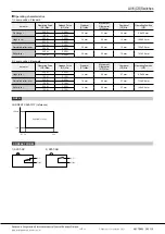
Страница 3: ...06 N Simulated roller lever 0 20 N 0 02 N 2 6 mm 0 8 mm 1 2 mm 12 2 0 8 mm 0 50 N 0 06 N Roller lever 0 20 N 0 02 N 2 6 mm 0 8 mm 1 2 mm 15 7 0 8 mm 0 50 N 0 06 N 2 Lever position Backward Actuator Operating Force OF Max Release Force RF Min Pretravel PT Max Movement Differential MD Max Overtravel OT Min Operating Position OP Hinge lever 0 35 N 0 03 N 1 4 mm 0 6 mm 0 7 mm 9 2 0 6 mm 1 00 N 0 10 N ...

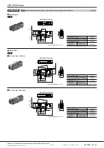
Страница 4: ...General tolerance 0 25 DIMENSIONS CAD The CAD data of the products with a CAD mark can be downloaded from our Website Unit mm CAD External dimensions Pin plunger Pretravel PT Max 0 6 mm Movement Differential MD Max 0 1 mm Overtravel OT Min 0 4 mm Operating Position OP Distance from mounting hole 8 4 0 3 mm CAD Lever position Standard External dimensions Hinge lever Pretravel PT Max 2 6 mm Movement...

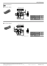
Страница 5: ...1 4 19 2 General tolerance 0 25 4 0 2 5 7 2 4 2 4 0 05 0 1 φ2 4 0 05 0 1 9 5 0 08 2 5 0 1 5 7 29 2 CAD Lever position Standard External dimensions Simulated roller lever Pretravel PT Max 2 6 mm Movement Differential MD Max 0 8 mm Overtravel OT Min 1 2 mm Operating Position OP Distance from mounting hole 12 2 0 8 mm Lever position Backward External dimensions Pretravel PT Max 1 4 mm Movement Differ...

Страница 6: ...External dimensions Pretravel PT Max 1 4 mm Movement Differential MD Max 0 6 mm Overtravel OT Min 0 7 mm Operating Position OP Distance from mounting hole 14 9 0 6 mm 2 5 OP 15 7 0 8 PT Max 2 6 General tolerance 0 25 7 φ2 4 0 05 0 1 2 5 0 1 9 5 0 08 5 7 29 2 7 7 10 0 2 4 0 05 0 1 12 9 18 CAD Lever position Standard External dimensions Roller lever Pretravel PT Max 2 6 mm Movement Differential MD M...

Страница 7: ...o not use any connector other than the specified connector or solder the terminals directly 2 Make sure leads are arranged so that no constant force is applied to them when the connectors are mated 3 Keep the connector straight when inserting it If it is inserted at an angle it may snag near the entrance or it may be inserted too forcefully 4 Problems thought to be caused by the XA connector which...

Страница 8: ...Electrical life The service life when the rated load is connected to the contact and switching operations are performed The life test is performed at a switching frequency of 20 times minute and operating speed of 100 mm second at the regular cam Contact form This refers to the components determining the type of application which make up the electrical input output circuits in the contact SPDT SPS...

Страница 9: ...equired to move from an operating position to a total travel position Movement Pretravel PT mm degree Max Distance or agree of the actuator movement from free position to operating position Overtravel OT mm degree Min The distance or degree which the actuator is permitted to travel after actuation without any damage to the switching mechanism Movement Differential MD mm degree Max The distance or ...

Страница 10: ...in contact failures or contact fusion 2 An extremely high activation speed may cause damage to contacts or contact response failure Driving Mechanism Use of a driving mechanism which will cause physical impact to the actuator should be avoided Example Bad Good TECHNICAL NOTES ON ELECTRICAL CHARACTERISTICS 1 The snap action switch is designed for AC operations While it has small contact gaps and no...

Страница 11: ... AC and DC Impedance of r is nearly equal to impedance of R C 0 1 μF R diode Contact for snap action switch 1 For DC circuits only ZNR Varistor Contact for snap action switch Induction load Can be used for both AC and DC 2 Do not connect the contacts on individual switches to different type or different poles of the power supply Examples of power supply connections connection to different poles PL...

Страница 12: ...ing hole 2 Depressed position The plunger lever should be pressed down to 70 or more of OT Over Travel Therefore the depressed position should be calculated based on the minimum value of OP Operating Position and the 70 and 100 of the OT value OP Min 70 of OT 8 0 0 84 7 16 mm OP Min 100 of OT 8 0 1 2 6 80 mm The plunger lever should be pressed down to the position of 6 80 to 7 16 mm from the mount...

Страница 13: ...sation can cause adverse conditions such as deterioration of insulation coil cutoff and rust Condensation or other moisture may freeze on the switch when the temperatures is lower than 0 C 32 F This causes problems such as sticking of movable parts or operational time lags The plastic becomes brittle if the switch is exposed to a low temperature low humidity environment for long periods of time St...

Страница 14: ...r is required Hinge lever Large Medium Small Possible Little force required for operation Appropriate for use with low speed cams and dogs has large stroke Lever available in various shapes to fit operating unit Simulated roller lever Large Medium Small Possible Tip of hinge lever is bent into a semi circle enabling use as a simple roller type Leaf lever Large Large Small Excellent Play in lever i...

Страница 15: ...Electromechanical Control Business Division industral panasonic com ac e Specifications are subject to change without notice 1006 Oaza Kadoma Kadoma shi Osaka 571 8506 Japan Panasonic Corporation 2021 AECTB60E 202110 ...

Отзывы: