Panasonic AKHC931BP - MULTI-FORMAT CAMERA Скачать руководство пользователя страница 2

2

CAUTION:

This product uses a semiconductor laser system 
and is a laser class 1 product complies with 
Radiation Performance Standards, 21CFR 
SUBCHAPTER J.
Use of controls or adjustments or performance 
of procedures other than those specified herein 
may result in hazardous radiation exposure.
Don’t make any modifications.
Don’t repair by yourself.
Refer servicing to qualified personnel.

CAUTION:

Invisible Laser radiation is emitted from the 
Optical fiber connector when this product is 
turned on.
Don’t look into directly into the Optical fiber 
connector of this product.

 indicates safety information.

CAUTION:

TO  REDUCE  THE  RISK  OF  FIRE  OR  SHOCK 
HAZARD  AND  ANNOYING  INTERFERENCE,  USE 
THE RECOMMENDED ACCESSORIES ONLY.

WARNING:

•  TO  REDUCE  THE  RISK  OF  FIRE  OR  SHOCK 

HAZARD, DO NOT EXPOSE THIS EQUIPMENT TO 
RAIN OR MOISTURE. 

•  TO  REDUCE  THE  RISK  OF  FIRE  OR  SHOCK 

HAZARD,  KEEP  THIS  EQUIPMENT  AWAY  FROM  
ALL  LIQUIDS.  USE  AND  STORE  ONLY  IN 
LOCATIONS WHICH ARE NOT EXPOSED TO THE 
RISK  OF  DRIPPING  OR  SPLASHING  LIQUIDS, 
AND  DO  NOT  PLACE  ANY  LIQUID  CONTAINERS 
ON TOP OF THE EQUIPMENT.

FCC Note:

This equipment has been tested and found to comply 
with the limits for a class A digital device, pursuant to 
Part 15 of the FCC Rules.  These limits are designed 
to  provide  reasonable  protection  against  harmful 
interference  when  the  equipment  is  operated  in  a 
commercial  environment.   This  equipment  generates, 
uses,  and  can  radiate  radio  frequency  energy,  and  if  
not  installed  and  used  in  accordance  with  the 
instruction  manual,  may  cause  harmful  interference 
to radio communications.  Operation of this equipment 
in  a  residential  area  is  likely  to  cause  harmful   
interference in which case the user will be required to 
correct the interference at his own expense.

Warning:

To  assure  continued  FCC  emission  limit  compliance, 
the user must use only shielded interface cables when 
connecting  to  external  units.    Also,  any  unauthorized 
changes or modifications to this equipment could void 
the user’s authority to operate it.

For your safety

CAUTION

RISK OF ELECTRIC SHOCK

 DO NOT OPEN

CAUTION: TO REDUCE THE RISK OF ELECTRIC SHOCK, 

DO NOT REMOVE COVER (OR BACK).

NO USER SERVICEABLE PARTS INSIDE.

REFER TO SERVICING TO QUALIFIED SERVICE PERSONNEL.

The  lightning  flash  with  arrowhead  symbol, 
within  an  equilateral  triangle,  is  intended  to 
alert  the  user  to  the  presence  of  uninsulated 
“dangerous  voltage”  within  the  product’s 
enclosure that may be of sufficient magnitude 
to  constitute  a  risk  of  electric  shock  to 
persons.
The  exclamation  point  within  an  equilateral 
triangle  is  intended  to  alert  the  user  to  the  
presence  of  important  operating  and 
maintenance  (service)  instructions  in  the 
literature accompanying the appliance.

This class A digital apparatus complies with 
Canadian ICES-003.
Cet  appareil  numérique  de  la  classe  A  est 
conforme à la norme NMB-003 du Canada.

For CANADA

This product contains a CR Coin Cell Lithium Battery 
which  contains  Perchlorate  Material  —  special 
handling may apply.
See www.dtsc.ca.gov/hazardouswaste/perchlorate.

Содержание AKHC931BP - MULTI-FORMAT CAMERA

Страница 1: ...Multi format camera AK HC931BP Before attempting to connect operate or adjust this product please read these instructions completely ...

Страница 2: ...iate radio frequency energy and if not installed and used in accordance with the instruction manual may cause harmful interference to radio communications Operation of this equipment in a residential area is likely to cause harmful interference in which case the user will be required to correct the interference at his own expense Warning To assure continued FCC emission limit compliance the user m...

Страница 3: ...ked on or pinched particularly at plugs convenience receptacles and the point where they exit from the apparatus 11 Only use attachments accessories specified by the manufacturer 12 Use only with the cart stand tripod bracket or table specified by the manufacturer or sold with the apparatus When a cart is used use caution when moving the cart apparatus combination to avoid injury from tip over 13 ...

Страница 4: ...5 Mounting the camera on a tripod 16 Component system configuration 17 System connections 1 with multi format camera 19 System connections 2 with build up unit 20 System connections 3 with MSU 21 Status displays on viewfinder screen 22 Menu operations 23 Setting menu configuration 25 How to select the video format 28 AK HC931BP connector pin assignment 29 External dimension drawings 30 Specificati...

Страница 5: ...e camera can be connected to existing peripheral devices no matter which video format is selected Newly developed 720P 2 3 million pixel CCDs incorporated This achieves a high sensitivity that surpasses the standard sensitivity of F10 and is on a par with SD Smear has been cut to 130 dB and the number of white marks has been drastically reduced by process improvements H CCD drive is accomplished a...

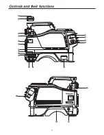
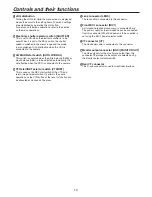
Страница 6: ...6 Controls and their functions ...

Страница 7: ...7 Controls and their functions ...

Страница 8: ... used to select the PGM to be mixed with INCOM2 INCOM2 PGM level control INCOM2 PGM This is used to adjust the INCOM2 and PGM mixing level RET A selector switch RET A This switch is used to select the return images to be switched by RET A RET B selector switch RET B This switch is used to select the return images to be switched by RET B CALL LED This lights when the CALL switch is pressed It also ...

Страница 9: ...en it is pressed again the optical filter can be controlled by the ROP Monitor output selector switch MONI SEL This is used to select the images Y C NAM R G B which are to be output from the monitor output connector ND filter selector knob This is used to adjust the optical filter manually when LOCAL has been selected as the filter setting 1 CAP 2 Through 3 1 4 4 1 16 5 1 64 CC filter selector kno...

Страница 10: ...sor to the setting items The menu settings are established by operating this dial button For details on the menu operations refer to the section on the menu operations Electronic shutter selector switch SHUTTER This is set to ON when the electronic shutter is to be used When it is set to the SEL position the shutter speed is switched in the preset range and the mode is also switched It is not effe...

Страница 11: ...ndling the lens refer to the instructions that accompany the lens Depending on the lens mounted it may be necessary to perform the following lens and camera adjustments 1 Flange back adjustment for the lens 2 Auto iris operation speed adjustment for the lens 3 White shading adjustment for the lens performed using the controls on the camera 1 Raise the lens clamp lever and remove the mount cap Moun...

Страница 12: ...ustment chart If the video level is too high use a filter or shutter 4 Loosen the screw that secures the F f flange focus ring Note Depending on the lens concerned this ring may be marked as the F b flange back ring 5 Set the zoom ring to the telephoto position either by manual or electrical means 6 Shoot the flange back adjustment chart and turn the distance ring to adjust the focus 7 Set the zoo...

Страница 13: ...late and slide the plate to attach the viewfinder 4 Tighten the stopper screw securely Detaching the viewfinder 1 Check that the camera s POWER switch is at the OFF position 2 Loosen the stopper screw pull up the knob on the mounting plate and slide the viewfinder along and off the plate 3 Disconnect the plug from the viewfinder cable connector Remove mounting plate from the viewfinder Mounting pl...

Страница 14: ...xing lever towards the outside to release it from the locked position 2 Move the viewfinder forward or backward to adjust its position 3 Rotate the viewfinder forward backward position fixing lever in the opposite direction until it locks Lever Viewfinder Forward or backward position adjustment Viewfinder Stopper screw Stopper screw Performing the viewfinder adjustments The viewfinder is an option...

Страница 15: ...en the microphone is mounted on the viewfinder optional accessory for use The microphone of the microphone kit AJ MC700P optional accessory can be mounted on the viewfinder MIC IN connector Microphone holder Clamp screw 4 If the audio channel whose signals are to be recorded so requires set the AUDIO IN switch to F AUDIO IN switch Connecting the microphone ...

Страница 16: ...ory to mount the camera on a tripod Tripod platform Tripod attachment Detaching the camera from the tripod attachment While pushing the red lever move the black lever in the direction of the arrow and slide the camera toward the back Note If the pin of the tripod attachment fails to return to its original position after the camera has been detached push the red lever again and simultaneously move ...

Страница 17: ... includes the lens multi format camera 2 viewfinder camera control unit CCU and remote operation panel ROP System block diagram 2 black and white viewfinder AJ HVF20P Build up unit AK HBU931P Large lens Microphone kit AJ MC700P Handy lens Multi format camera AK HC931BP Tripod attachment SHAN TM700 SD memory card RP SD008B Master setup unit AK MSU930P 8 LCD viewfinder AK HVF931P Remote operation pa...

Страница 18: ...ely or simultaneously by remote control It can be operated together with the ROP 4 2 viewfinder 2 VF AJ HVF20P This is the viewfinder for the multi format camera 5 Build up unit AK HBU931P This is an adapter used to mount a larger lens optional accessory on the multi format camera Thereby it affords the same level of operability as that provided by a larger camera 6 LCD viewfinder LCD VF AK HVF931...

Страница 19: ...power switch is set to ON after the CCU main power switch has been set to ON the camera can be controlled using the ROP Upon completion of shooting set the CCU camera power switch and main power switch to OFF 2 viewfinder AJ HVF20P Lens Multi format camera AK HC931BP ROP cable Remote operation panel AK HRP931P Camera control unit AK HCU931P System connections 1 with multi format camera ...

Страница 20: ...rge lens Build up unit AK HBU931P 8 LCD viewfinder AK HVF931P Multi format camera AK HC931BP Remote operation panel AK HRP931P Camera control unit AK HCU931P ROP cable System connections 2 with build up unit ...

Страница 21: ... Multi format camera AK HC931BP Camera control unit 14 AK HCU931P Camera control unit 15 AK HCU931P Remote operation panel 14 AK HRP931P Remote operation panel 15 AK HRP931P Build up unit AK HBU931P A multiple number of cameras up to 15 units can be controlled in one location using the MSU The cameras can be controlled by both the ROPs and MSU System connections 3 with MSU ...

Страница 22: ...use Filter display This indicates the type of filter selected White balance memory display This indicates the automatic adjustment memory selected for the white balance A The WHITE BAL switch is set to A B The WHITE BAL switch is set to B P The WHITE BAL switch is set to PRST Gain display This indicates the video amplifier s gain setting in dB which has been selected by the GAIN switch Audio CH1 a...

Страница 23: ...urn the JOG dial to select the menu item to be set 2 Turn the JOG dial to select the menu item 3 After having selected the item press the JOG dial to access that item s menu 2 When the JOG dial is pressed the setting of the item indicated by the arrow flashes 3 Turn the JOG dial to change the setting 4 When the JOG dial is pressed the data is entered Note Bear in mind that if in step 3 the MENU sw...

Страница 24: ...es one character at a time press the JOG dial to move the flashing toward the right 1 When the JOG dial is pressed flashing moves toward the right 2 Turn the JOG dial to change the setting 3 When the JOG dial is now pressed the data is entered Menu operations ...

Страница 25: ...25 Hierarchical menus Setting menu configuration ...

Страница 26: ...26 Hierarchical menus Setting menu configuration ...

Страница 27: ...27 Hierarchical menus Setting menu configuration ...

Страница 28: ...RMAT SEL and press the JOG dial Yes and No now appear at the center of the screen 4 Select Yes and press the JOG dial The TURN OFF POWER message is now displayed To cancel the selection of the video format select No and press the JOG dial The arrow now returns to the FORMAT SEL position 5 While the TURN OFF POWER message is displayed turn off the camera s power and then turn it back on The camera ...

Страница 29: ...ND 2 MIC1 H 3 MIC1 C MIC2 HA16PRM 3SB 05 Hirose Pin Signal 1 MIC2_GND 2 MIC2 H 3 MIC2 C TALLY OUT HR10A 7R 4SC Hirose Pin Signal 1 UNREG_GND 2 R_TALLY_OUT 3 G_TALLY_OUT 4 SCRIPT 12V EARPHONE VJJ0522 Pin Signal 1 PHONE_GND 2 PHONE_OUT 3 TRUNK HR10A 10R 12SC Hirose Pin Signal 1 CMD OUT0 H 2 CMD OUT0 C 3 CMD IN0 H 4 CMD IN0 C 5 CMD OUT1 H 6 CMD OUT1 C 7 CMD IN H 8 CMD IN1 C 9 10 DGND 11 12 LENS HR10A...

Страница 30: ...30 14 3 8 365 mm 11 1 16 280 mm 9 1 8 231 5 mm 5 126 mm External dimension drawings Unit inch mm ...

Страница 31: ...trusions 126 280 365 mm Basic items 1 Pickup device 2 3 million pixel ITCCD 3 2 System GBR pickup system 3 Color separation optical system f 1 4 prism 4 Optical filters CC 3200K 4300K 6300K Cross Diffusion ND CAP Through 1 4 1 16 1 64 5 Lens mount Bayonet type 6 Output standard SMPTE 296M 274M 7 Sensitivity f 10 0 2000 lux 3200 K white reflectance 89 9 8 Horizontal modulation More than 45 27 5 MHz...

Страница 32: ...arketing Department 52 West Gude Drive Rockville MD 20850 301 738 3840 Broadcast PARTS INFORMATION ORDERING 9 00 a m 5 00 p m PST 800 334 4881 24 Hr Fax 800 334 4880 Emergency after hour parts orders 800 334 4881 TECHNICAL SUPPORT Emergency 24 Hour Service 800 222 0741 Panasonic Canada Inc 5770 Ambler Drive Mississauga Ontario L4W 2T3 905 624 5010 Panasonic de Mexico S A de C V Av angel Urraza Num...

Отзывы: