background image

26

Setup menus

USER menu

<INTERFACE>

Item

Setting

No.

Superimposed

No.

Superimposed

Description

display

display

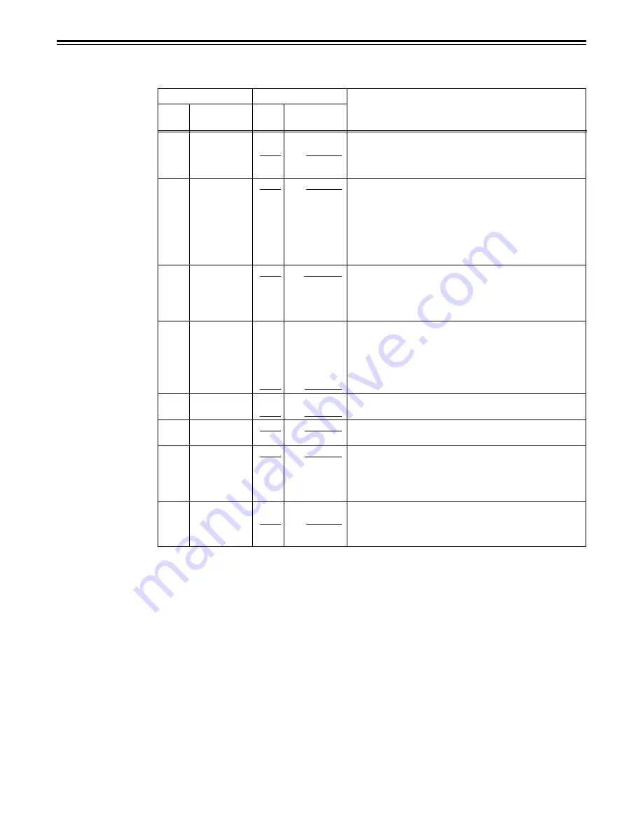
201

9P SEL

0000

OFF

0001

        ON

202

ID SEL

0000

 OTHER

0001

DVCPRO

0002

ORIG

204

RS232C SEL

0000

       OFF

0001

ON

205

BAUD RATE

0000

300

0001

600

0002

1200

0003

2400

0004

4800

0005

      9600

206

DATA

0000

7

LENGTH

0001

            8

207

STOP BIT

0000

            1

0001

2

208

PARITY

0000

      NON

0001

ODD

0002

EVEN

209

RETURN

0000

OFF

ACK

0001

        ON

The underline on the setting item denotes the initial setting.

This selects whether the 9-Pin connector functions when the
REMOTE/LOCAL switch has been set to REMOTE.
0: Do not function
1: Function

This selects the ID information which is returned to the
controller.
0: 20  25H
1: DVCPRO’s, own ID is returned (F0 33H).
2: The unit’s own ID (A0 3CH) is returned.
<Note>
Set “ORIG” only when the unit is connected with a Panasonic
controller (such as the AJ-A900, optional accessory).

These settings are for selecting whether the RS-232C con-
nector is to function when the REMOTE/LOCAL switch is set
to REMOTE.
0: Connector does not function.
1: Connector functions.

These settings are for selecting the RS-232C communication
speed (baud rate).

These settings are for selecting the RS-232C data length.
(Unit: bit)

These settings are for selecting the RS-232C stop bit length.
(Unit: bit)

These settings are for selecting the none, odd or even for the
RS-232C parity bit.
0: Parity bit is not used.
1: An odd number of bits is used for the parity system.
2: An even number of bits is used for the parity system.

These settings are for selecting whether the ACK code is to be
returned when a command is received from RS-232C.
0: ACK code is not returned.
1: ACK code is returned.

Содержание AJ-D455

Страница 1: ...Panasonic Broadcast AJ D455 Menu Information...

Страница 2: ...oves and the item No on the display flashes When the button is pressed the item No is incremented for 001 002 003 004 and so on when the button is pressed the item No is decremented 3 Press the cursor...

Страница 3: ...cursor button to switch to the previous user file SYSTEM USER 1 USER 2 USER 3 USER 4 USER 5 USER FILE Each user file contains the following items BASIC OPERATION INTERFACE EDIT TAPE PROTECT TIME CODE...

Страница 4: ...etup menu item No A03 MENU LOCK for the system or user file 4 Press the or button and select lock mode setting or release To set the lock Select the 0001 ON setting To release the lock Select the 0000...

Страница 5: ...END 4 Press the or button and select the user file whose contents are to be loaded into USER1 5 Press the SET button The following messages appear on the menu screen and counter display Menu screen Co...

Страница 6: ...display S U1 U2 SETUP MENU SAVE USER1 USER2 OK YES PLAY NO STOP The user file number selected in step 4 is displayed in the shaded area 6 Press the PLAY button The contents of the USER1 file are save...

Страница 7: ...factory default setting System phase adjustment SC period increments 15 s variable range Advanced Delayed Note If setting operation is performed the setting value does not return to factory default s...

Страница 8: ...vel can be varied is from 3 to 3 dB For adjusting the system phase offset 4 48 s steps 0 13 4 s 1 8 96 s 2 4 48 s 3 0 4 4 48 s 5 8 96 s 6 13 4 s Notes The setting remains unchanged even when the facto...

Страница 9: ...hen setting this item the DISPLAY SEL status is output to VIDEO OUT 3 SERIAL OUT 3 even if SUPER OFF has been set However when the menu is exited operation complies with the SUPER OFF ON setting Also...

Страница 10: ...ith a black border For selecting whether to display the remaining tape time and total tape length as the superimposed display at the VIDEO OUT 3 SERIAL OUT 3 connector 0 No display appears 1 Remaining...

Страница 11: ...n switches from the stop or search modes to the play mode 0 The time until the audio is output is shortened 1 The audio is output after the status stabilizes Note When set to 0 OFF the sound in the in...

Страница 12: ...REW function takes precedence This selects whether to allow enable or prohibit disable the recording of signals on the cassette tape 0 Signals can be recorded on the cassette tape when the cassette s...

Страница 13: ...H 2 The unit s own ID A0 3CH is returned Note Set ORIG only when the unit is connected with a Panasonic controller such as the AJ A900 optional accessory These settings are for selecting whether the R...

Страница 14: ...audio signals designated by the controller 0 Not set 1 Compliance with analog CH1 edit preset 2 Compliance with analog CH2 edit preset 3 Compliance with either analog CH1 or CH2 edit preset This sets...

Страница 15: ...re used This selects the VAR speed during remote control operations 0 The tape is played at the fine step speed 1 The tape is played at a speed at which noise less playback is possible in the 0 43 to...

Страница 16: ...the maximum JOG FWD speed 0 4 1 3 1 speed 1 1 85 1 85 speed 2 1 1 speed Notes The speeds in parentheses apply when a DV or DVCAM cassette is used At any speed setting other than 0 4 1 the phase cannot...

Страница 17: ...ding in the still status 0 STEP FWD 1 HALF LOADING Note When STEP FWD is selected operation will be automatically transferred to the standby OFF half loading mode as soon as the unit has been left sta...

Страница 18: ...nd user bit are regenerated 1 Only the time code is regenerated 2 Only the user bit is regenerated This selects whether values used in the internal time code generator are preset from the front panel...

Страница 19: ...ting controller This selects the DF NDF mode for CTL and TCG 0 Drop frame mode 1 Non drop frame mode Note No 509 is valid when the CONTROL is LOCAL or LOCAL ENA of item 004 to ENA This selects the tim...

Страница 20: ...e forcibly processed as B W signals 1 The signals are automatically processed This selects whether to float the vertical sync position of the video output in order to align the video output phase with...

Страница 21: ...ignals regardless of whether the WIDE information is on the tape Forced WIDE ON 2 During recording the WIDE information is not recorded on the tape regardless of whether the S1 VIDEO input signals con...

Страница 22: ...signal to be recorded on the audio CH2 track 0 Audio input CH1 signal 1 Audio input CH2 signal 2 Mixed audio input CH1 and CH2 signal This selects the input signal recorded in CUE 0 The signal selecte...

Страница 23: ...output in the 0 43 to 1 speed range in all other cases CUE is automatically output Note The PCM AUDIO output CH1 and CH2 signals are output separately regardless of the position selected for the AUDI...

Страница 24: ...the USER1 settings will be saved 0 The settings are saved in USER2 1 The settings are saved in USER3 2 The settings are saved in USER4 3 The settings are saved in USER5 4 This display appears when al...

Отзывы: