background image

3

Important Safeguards

1 ) Read Instructions — All the safety and operating 

instructions should be read before the unit is operated.

2 ) Retain Instructions — The safety and operating 

instructions should be retained for future reference.

3 ) Heed Warnings — All warnings on the unit and in the 

operating instructions should be adhered to.

4 ) Follow Instructions — All operating and maintenance 

instructions should be followed.

5 ) Cleaning — Unplug this video unit from the wall outlet 

before cleaning. Do not use liquid or aerosol cleaners. 
Use a dry cloth for cleaning.

6 ) Attachments — Do not use attachments not 

recommended by the video product manufacturer as 
they may be hazardous.

7 ) Water and Moisture — Do not use this video unit near 

water- for example near a bath tub, wash bowl, kitchen 
sink, or laundry tub, in a wet basement, or near a 
swimming pool, and the like.

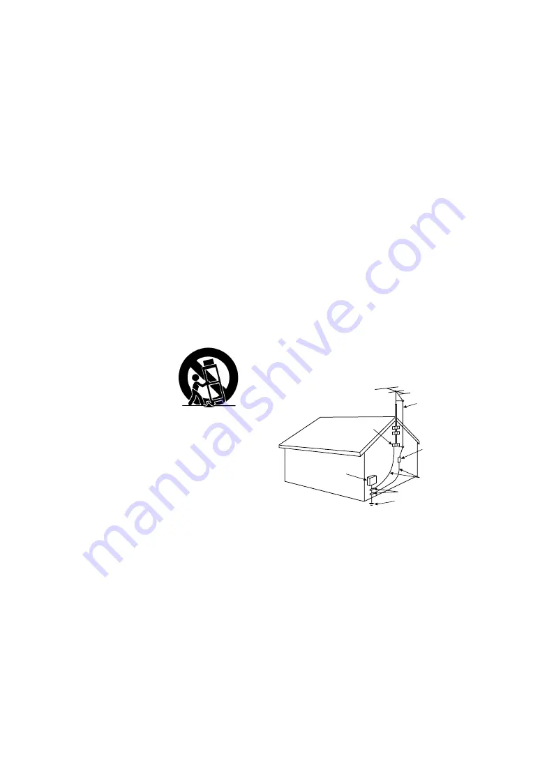
8 ) Accessories — Do not place this video unit on an 

unstable cart, stand, tripod, bracket, or table. The video 
unit may fall, causing serious injury to a child or adult, 
and serious damage to the unit. Use only with a cart, 
stand, tripod, bracket, or table recommended by the 
manufacturer, or sold with the video unit. Any mounting 
of the unit should follow the manufacturer’s instructions 
and should use a mounting 
accessory recommended by the 
manufacturer. An appliance and 
cart combination should be 
moved with care. Quick stops, 
excessive force, and uneven 
surfaces may cause the 
appliance and cart combination 
to overturn.

9 ) Ventilation — Slots and openings in the cabinet are 

provided for ventilation and to ensure reliable operation 
of the video unit and to protect it from overheating. 
These openings must not be blocked or covered. Never 
place the video unit on a bed, sofa, rug, or other similar 
surface, or near or over a radiator or heat register. This 
video unit should not be placed in a built-in installation 
such as a bookcase or rack unless proper ventilation is 
provided or the manufacturer’s instructions have been 
adhered to.

10) Power Sources — This video unit should be operated 

only from the type of power source indicated on the 
marking label. If you are not sure of the type of power 
supply to your home, consult your appliance dealer or 
local power company. For video units intended to be 
operated from battery power, or other sources, refer to 
the operating instructions.

11) Grounding or Polarization — This video unit may be 

equipped with either a polarized 2-wire AC (Alternating 
Current) line plug (a plug having one blade wider than 
the other) or 3-wire grounding type plug, a plug having a 
third (grounding) pin.
The 2-wire polarized plug will fit into the power outlet 
only one way. This is a safety feature. If you are unable 
to insert the plug fully into the outlet, try reversing the 
plug. If the plug still fails to fit, contact your electrician to 
replace your obsolete outlet. Do not defeat the safety 
purpose of the polarized plug.
The 3-wire grounding type plug will fit into a grounding 
type power outlet. This is a safety feature. If you are 
unable to insert the plug into the outlet, contact your 
electrician to replace your obsolete outlet. Do not defeat 
the safety purpose of the grounding type plug.

12) Power-Cord Protection — Power-supply cords should be 

routed so that they are not likely to be walked on or 
pinched by items placed upon or against them, paying 
particular attention to cords of plugs, convenience 
receptacles, and the point where they exit from the unit.

13) Outdoor Antenna Grounding — If an outside antenna or 

cable system is connected to the video unit, be sure the 
antenna or cable system is grounded so as to provide 
some protection against voltage surges and built-up 
static charges. Part 1 of the Canadian Electrical Code, in 
USA Section 810 of the National Electrical Code, 
provides information with respect to proper grounding of 
the mast and supporting structure, grounding of the lead 

in wire to an antenna discharge unit, size of grounding 
conductors, location of antenna discharge unit, 
connection to grounding electrodes, and requirements 
for the grounding electrode.

14) Lightning — For added protection of this video unit 

receiver during a lightning storm, or when it is left 
unattended and unused for long periods of time, unplug 
it from the wall outlet and disconnect the antenna or 
cable system. This will prevent damage to the video unit 
that may be caused by lightning and power-line surges.

15) Power Lines — An outside antenna system should not 

be located in the vicinity of overhead power lines or other 
electric light or power circuits, or where it can fall into 
such power lines or circuits. When installing an outside 
antenna system, extreme care should be taken to keep 
from touching such power lines or circuits as contact with 
them might be fatal.

16) Overloading — Do not overload wall outlets and 

extension cords as this can result in a risk of fire or 
electric shock. 

GROUND
CLAMP

ANTENNA
LEAD IN
WIRE

ANTENNA
DISCHARGE UNIT
(NEC SECTION 810 - 20)

GROUNDING CONDUCTORS
(NEC SECTION 810 - 21)

GROUND CLAMPS

POWER SERVICE GROUNDING
ELECTRODE SYSTEM
(NEC ART 250, PARTH)

NEC

 - NATIONAL ELECTRICAL CODE

ELECTRIC
SERVICE
EQUIPMENT

Содержание AGEZ50UP - DIGITAL CAMERA REC

Страница 1: ...Digital Video Camera Recorder Operating Instructions Model No AG EZ50UP R Before attempting to connect operate or adjust this product please read these instructions thoroughly VQT9420 Mini...

Страница 2: ...s However there is no guarantee that interference will not occur in a particular installation If this equipment does cause harmful interference to radio or television reception which can be determined...

Страница 3: ...lug having one blade wider than the other or 3 wire grounding type plug a plug having a third grounding pin The 2 wire polarized plug will fit into the power outlet only one way This is a safety featu...

Страница 4: ...ZARD Your Camera Recorder and power supply should not be exposed to rain or moisture Do not connect the power supply or operate your Camera Recorder if it gets wet Your Camera Recorder has been design...

Страница 5: ...Balance 25 Adjusting White Balance Manually 25 Digital Effect Functions 26 VCR Mode Playing Back 28 Finding a Scene You Want to Play Back 28 Slow Motion Playback 29 Still Playback Still Advance Playb...

Страница 6: ...0 220 240V AC An AC plug adaptor may be required for voltages other than 120V AC Please contact either a local or foreign electrical parts distributor for assistance in selecting an alternate AC plug...

Страница 7: ...Lever to the right and pull down to open the Cassette compartment cover Insert the Cassette Press the PUSH TO CLOSE 3 to load the Cassette Close the lower compartment Cover 5 Start recording l 20 Pres...

Страница 8: ...ng Check Button S l 20 10 Title Button TITLE l 37 11 Multi Picture Button MULTI l 27 32 36 37 Picture in Picture Button P IN P l 27 12 Speaker 13 Microphone built in stereo 14 Focus Ring l 23 15 Lens...

Страница 9: ...limitations in LCD production technology there may be some tiny bright or dark spots on the Viewfinder screen However this is not a malfunction and does not affect the recorded picture 43 Upper Casset...

Страница 10: ...ounter Reset Button RESET l 52 4 Indication Shift Button COUNTER l 45 5 Multi Picture Picture in Picture Button MULTI P IN P l 27 32 36 37 6 Recording Button REC l 41 42 7 Audio Dubbing Button A DUB l...

Страница 11: ...lace battery with CR2025 only Use of another battery may present a risk of fire or explosion Caution Battery may explode if mistreated Dispose of used battery promptly Keep away from children Do not r...

Страница 12: ...mp lights up and charging starts When the CHARGE Lamp goes off charging is completed 2 Attach the charged Battery to the Camera Recorder Disconnecting the Power Source Set the OFF ON MODE Switch to OF...

Страница 13: ...he Camera Recorder and pull the Shoulder Strap 2 Fold the tip of the Shoulder Strap pass it through the Shoulder Strap Length Adjuster and pull it Pull it out more than 1 inch 2 cm 2 from the Shoulder...

Страница 14: ...ON 2 Slide the PUSH OPEN Lever and at the same time bring out the LCD Monitor about 90x in the direction of the arrow The Viewfinder goes off 3 Adjust the LCD Monitor angle according to the desired r...

Страница 15: ...4 on the Remote Controller To select items on the Menu press the ITEM Button 5 on the Remote Controller To set the mode for the selected items press the SET Button 6 on the Remote Controller To Exit t...

Страница 16: ...Stabilizer EIS l 22 4 Digital Zoom D ZOOM l 22 5 Recording Mode REC MODE l 21 6 Returning to the Main Menu RETURN DIGITAL EFFECT Sub Menu 7 Digital Effects 1 EFFECT1 l 26 8 Digital Effects 2 EFFECT2 l...

Страница 17: ...o Selector AUDIO OUT l 48 6 Returning to the Main Menu RETURN DIGITAL EFFECT Sub Menu 7 Digital Effect On Off EFFECT l 31 32 8 Digital Effect Selection EFFECT SELECT l 31 32 CARD SETUP Sub Menu 9 Pict...

Страница 18: ...URE menu for erasing the displayed picture appears Use this menu after the picture to be erased has appeared 11 FILE LOCK The FILE LOCK menu to prevent the accidental erasure of the displayed picture...

Страница 19: ...lithium battery and reset the date and time Internal Lithium Battery Recharge The internal lithium battery sustains the operation of the clock When the 0 Indication is lit the internal lithium battery...

Страница 20: ...tes see page 46 To View the recorded scene while the Recording is paused Camera Search The recorded scene can be viewed by holding down the sSEARCH Button 7 or rSEARCH Button 8 in the Recording Pause...

Страница 21: ...sed For normal recording set REC MODE to NORMAL Continuous Photoshot If the PHOTO SHOT Button is held down with the SHUTTER of the Sub Menu OTHER FUNCTIONS set to ON the Camera Recorder will record st...

Страница 22: ...tion in these images If the Camera Recorder shakes too much this Function may not be able to stabilize images 1 Set CAMERA FUNCTIONS CAMERA SETUP EIS ON The EIS Indication 1 appears Canceling Optical...

Страница 23: ...Mode 2 Focuses on the main subject of the image and leaves the background slightly out of focus 4 Low Light Mode 3 Preserves the mood of dim light settings without altering picture brightness Spotlig...

Страница 24: ...cted the image becomes darker When a value closer to OPEN18dB is selected the image becomes brighter The value to which dB is attached indicates a gain value If this value is too large the quality of...

Страница 25: ...ion appears after the screen has darkened for a moment When the 1 Indication flashes after turning the Camera Recorder on the previously adjusted white balance setting is still kept To Resume Automati...

Страница 26: ...h a painting like effect Selecting a desired digital effect Set CAMERA FUNCTIONS DIGITAL EFFECT EFFECT1 or EFFECT2 a desired digital effect Canceling the digital effect Set CAMERA FUNCTIONS DIGITAL EF...

Страница 27: ...the Recording Start Stop Button or the PHOTOSHOT Button to record on the Cassette Deleting all the captured Multi pictures While 9 multi pictures are displayed press the MULTI Button If MANUAL has bee...

Страница 28: ...ack press the 5 Button or the 6 Button only briefly As this locks the search function you do not need to keep the button pressed for a long time To resume normal playback press the 1 Button During Cue...

Страница 29: ...Dial PUSH Dial 1 of the Camera Recorder in the Still Playback Mode still pictures can be advanced one frame at a time in the forward or backward direction If the Camera Recorder is left in the Still P...

Страница 30: ...DEX PHOTO 2 Press the 9 Button 1 or the Button 2 on the Remote Controller With each press of the corresponding button still pictures recorded in Photoshot Mode are searched After Pictures with Sounds...

Страница 31: ...lected effect s indication flashes Canceling the Digital Effect Press the SELECT Button on the Remote Controller repeatedly until the Digital Effect Indication is cleared For other notes see page 47 P...

Страница 32: ...ress the MULTI Button If STROBE is selected 9 screens are automatically captured starting at the point which the Button is pressed If MANUAL is selected press the MULTI Button at each scene you want t...

Страница 33: ...as recorded with AUDIO REC on the RECORDING SETUP Sub Menu of the CAMERA FUNCTIONS Main Menu set to 16bit the original sound is erased If you want to preserve the original sound use the 12bit Mode whe...

Страница 34: ...Photoshot Recording a picture through the Camera Recorder lens CAMERA Mode 1 Slide the TAPE CARD Selector to CARD 2 Set PICTURE SIZE on the CARD SETUP Sub Menu to 1488t1128 or 640t480 If you select 1...

Страница 35: ...layed back for approximately 5 seconds each from the first to the last recorded picture and the playback then stops To Pause the Slide Playback Press the Button The SLIDE Indication is displayed 5 To...

Страница 36: ...cted number s picture appears The same setting can be performed using the short cut menu l 18 For other notes see page 48 Copying pictures from a Memory Card to a Cassette After setting to the Card Pl...

Страница 37: ...e green cyan red pink yellow and white Title in a preset color in which the dark portion blackish portion of the captured image is missing 3 Original color the color of the captured image Title in the...

Страница 38: ...res recorded on a Memory Card Using the Camera Recorder you can delete the still pictures and titles recorded on a Memory Card After the picture has been deleted it cannot be restored After setting to...

Страница 39: ...sed with any system that provides DPOF After setting to the Card Playback Mode l 35 1 Set CARD FUNCTIONS CARD EDITING DPOF SETTING YES 2 Rotate the PUSH Dial to select VARIABLE and then press it 3 Rot...

Страница 40: ...diaCard s by this Camera Recorder conform with DCF Design Rules for Camera Files Systems universal standard established by JEIDA Japan Electronic Industry Development Association If you attempt to pla...

Страница 41: ...Other Equipment 3 Insert a recorded Cassette and start playback Camera Recorder 4 While pressing the REC Button press the PLAY Button Both buttons are located on the Remote Controller 5 Press the Butt...

Страница 42: ...ode Playback Unit A 3 Press the 1 Button to start playback Recording Unit B 4 While pressing the REC Button press the PLAY Button Both Buttons are located on the Remote Controller Recording starts Sto...

Страница 43: ...Speed Mode SP Standard Play Mode l 19 LP Long Play Mode l 19 7 Index For several seconds while index signals are being recorded the INDEX Indication flashes l 30 Search Number S 1 l 30 The figure ind...

Страница 44: ...ind Noise Reduction WIND CUT l 16 Progressive Photoshot Mode l 21 18 File Type Display PICTURE TITLE l 35 37 19 File Name Display l 35 36 37 20 Card Picture Indications 1 DPOF setting setting for 1 or...

Страница 45: ...is Indication will appear for approximately 5 seconds If this Indication appears return the LCD Monitor to the original position in order to check the specific content of the Warning Alarm Indication...

Страница 46: ...You cannot use the Progressive Photoshot Function in the following circumstances When the zoom magnification is approximately 10 t or higher When the shutter speed is 1 750 or faster When EFFECT1 is s...

Страница 47: ...case using the Digital Effect Function including Multi Picture Mode P IN P Mode is not possible Card Photoshot Mode Wipe Mode and Mix Mode Camera Mode l 26 If either one of the following operations is...

Страница 48: ...n the Card Photoshot mode the Camera Recorder automatically saves the file names Imga0001 jpg etc along with the pictures A file name is recorded with each picture as a running number Recording to a C...

Страница 49: ...e Care should be taken when inserting and ejecting the Cassette Do not spray insecticides or volatile chemicals onto the Camera Recorder If the Camera Recorder is sprayed with such chemicals the Camer...

Страница 50: ...t Steps 1 to 3 Do not use the Head Cleaner for 3 times or more consecutively Notes Do not rewind every time you use the Head Cleaner Rewind only when the tape reaches the end and then use it again fro...

Страница 51: ...or Viewfinder Lens Hood LCD Monitor In a place with drastic temperature changes condensation may take place on the LCD Monitor Wipe it with soft dry cloth If your Camera Recorder is extremely cold whe...

Страница 52: ...fect of light on the subject s color what is called White Balance Adjustment becomes necessary White Balance Adjustment White Balance Adjustment recognizes the color of light and makes adjustment so t...

Страница 53: ...0 Vp p 75 ohm S Video Output Level Y Output 1 0 Vp p 75 ohm C Output 0 286 Vp p 75 ohm Audio Output Level 316 mV 600 ohm Video Input Level 1 0 Vp p 75 ohm S Video Input Level Y Input 1 0 Vp p 75 ohm...

Страница 54: ...echargeable Lithium Ion Battery Pack 5300mAh Rechargeable Lithium Ion Battery Pack Figure BN SDCAPU 1B BN SDABPU 1B USB Reader Writer for SD Memory Card compatible with MultiMediaCard SD PCMCIA Adapto...

Страница 55: ...The Battery cannot be charged If the DC Cable is connected to the AC Adaptor charging cannot be performed Disconnect the DC Cable Recording does not start although power is supplied to the Camera Reco...

Страница 56: ...unds separately The original sound was erased when audio dubbing was performed If you perform audio dubbing on a recording done in 16bit Mode the original sound will be erased If you want to preserve...

Страница 57: ...Still Picture Recording 34 Memory Card 34 Memory Stop Function 52 Menu Screen 15 Microphone 48 Mirror Mode Digital Effect 26 31 Mix Mode 26 31 Mosaic Mode 26 31 Multi Picture Mode 27 32 N Negative Mod...

Страница 58: ...W Los Angeles CA 90068 323 436 3500 Government Marketing Department 52 West Gude Drive Rockville MD 20850 301 738 3840 Broadcast PARTS INFORMATION ORDERING 9 00 a m 5 00 p m EST 800 334 4881 24 Hr Fax...

Отзывы: