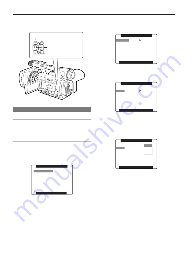
background image

28

Basic operations of setup menus

Use the setup menus to change the settings to 
suit the scenes you are shooting or what you are 
recording.

Operation lever

MENU button

Using the menus

• Set to CAMERA mode if the camera is 

operating in another mode. (Page 74 of Vol. 2)

• The menu items indicated in the blue 

characters cannot be used.

1

  Press the MENU button when not recording 

in CAMERA mode.

The following is displayed on the viewfinder 
and LCD screen.

PUSH  MENU  TO  EXIT 

2.SYSTEM SETUP

3.SW MODE

4.AUTO SW

5.RECORDING SETUP

6.AUDIO SETUP

7.OUTPUT SEL

8.DISPLAY SETUP

1.SCENE FILE

MAIN MENU

2

  Push the Operation lever in the ▲ or ▼ 

direction to move the highlight to the 

setting you want.

3

  Press SET on the Operation lever (or push 

it in the ► direction) to display the items.

Example:

PUSH  MENU  TO  RETURN 

AGC

ATW

AF

ON

6dB

ON

ON

A.IRIS

AUTO  SW

4

  Push the Operation lever in the ▲ or ▼ 

direction to move to the setting you want.

Example:

PUSH  MENU  TO  RETURN 

AGC

ATW

AF

ON

6dB

ON

ON

A.IRIS

AUTO  SW

5

  Press SET on the Operation lever to 

confirm the setting.

To change a value, push the Operation lever in
the 

 or 

 direction to change as necessary.

Example:

PUSH  MENU  TO  RETURN 

AGC

ATW

AF

6dB

12dB

18dB

OFF

A.IRIS

AUTO  SW

6

  To change other settings, repeat steps 4 

and 5.

When you finish, press the MENU button to
return to the function screen.

7

  To change other functions, repeat steps 2 

to 5.

When you exit the menu mode, press the 
MENU button again to return to the normal 
screen.

Menu

Содержание AG-HPX255P

Страница 1: ...Instructions Vol 1 Memory Card Camera Recorder Model No AG HPX255P Model No AG HPX255EN Note that Operation Instructions Vol 1 describes basic operations of the Memory Card Camera Recorder For instructions on advanced operations of the Memory Card Camera Recorder refer to Operating Instructions Vol 2 pdf file contained in the supplied CD ROM Volume 1 Before operating this product please read the i...

Страница 2: ...ws microphone holder adapter INPUT terminal covers out of the reach of babies and small children CAUTION To reduce the risk of fire or electric shock and annoying interference use the recommended accessories only CAUTION Do not jar swing or shake the unit by its handle Any strong jolt to the handle may damage the unit or result in personal injury CAUTION The mains plug of the power supply cord sha...

Страница 3: ...iate radio frequency energy and if not installed and used in accordance with the instructions may cause harmful interference to radio communications However there is no guarantee that interference will not occur in a particular installation If this equipment does cause harmful interference to radio or television reception which can be determined by turning the equipment off and on the user is enco...

Страница 4: ... where they exit from the apparatus 11 Only use attachments accessories specified by the manufacturer 12 Use only with the cart stand tripod bracket or table specified by the manufacturer or sold with the apparatus When a cart is used use caution when moving the cart apparatus combination to avoid injury from tip over 13 Unplug this apparatus during lightning storms or when unused for long periods...

Страница 5: ... Apenas Manuseio de baterias usadas Cobrir os terminais positivo e negativo com uma fita isolante adesiva antes de depositar numa caixa destinada para o recolhimento O contato entre partes metálicas pode causar vazamentos gerar calor romper a blindagem e produzir fogo Não desmonte não remova o invólucro nem amasse a bateria O gás liberado pela bateria pode irritar a garganta danificar o lacre do i...

Страница 6: ...ins plug of the power supply cord shall remain readily operable The AC receptacle mains socket outlet shall be installed near the equipment and shall be easily accessible To completely disconnect this equipment from the AC mains disconnect the power cord plug from the AC receptacle CAUTION Danger of explosion or fire if battery is incorrectly replaced or mistreated Do not disassemble the battery o...

Страница 7: ... apparatus is equivalent to or better than the performance level required by these standards However the apparatus may be adversely affected by interference if it is being used in an EMC environment such as an area where strong electromagnetic fields are generated by the presence of signal transmission towers cellular phones etc In order to minimize the adverse effects of the interference on the a...

Страница 8: ...logy Both SD Memory Cards and SDHC Memory Cards as referred to as SD Memory Cards in these operating instructions Memory cards that have the P2 logo e g AJ P2C064AG an optional accessory are referred to as P2 cards in these operating instructions Video that is created during a single recording operation is referred to as a clip in these operating instructions 1 Please note that this extended warra...

Страница 9: ...ates Slow quick motion recording Maximum 4 channel uncompressed digital audio recording DV recording 480i 576i For details on how to handle recorded data see Page 161 of Vol 2 1 P2 mode shooting and playback Page 10 of Vol 2 Page 74 of Vol 2 Personal Computer The data file is transferred for nonlinear editing on your personal computer or other unit 2 USB device mode Page 109 of Vol 2 External hard...

Страница 10: ...ng the battery 20 Charging 20 Power sources 21 Using the battery 21 Using the AC adaptor 21 Adjusting the hand strap 22 Attaching the shoulder strap 22 Detaching and attaching the lens hood 22 Detaching and attaching the lens cap 23 Fitting the eye cup 23 The remote control 24 Insert the battery 24 Remote control setup 24 Turn on off the camera recorder 25 Setting the calendar 26 Charging the buil...

Страница 11: ...ode USB device Using a hard disk drive PC mode USB host Displays Screen displays Menu Setup menu list Reference Before calling for service Updating the firmware incorporated into the unit Cleaning Storage precautions How to handle data recorded on P2 cards Checkpoints for using memory cards Information on software for this product Recording format list Cautions in using the Extension Control Unit ...

Страница 12: ... and dust can damage the camera recorder or a card Be especially careful when inserting or removing a card Battery charger and battery If the CHARGE lamp continues to blink even when the battery temperature is normal there may be something wrong with the battery or battery charger Contact your dealer The battery takes longer to charge when it is warm The battery charger can interfere with radio re...

Страница 13: ...ll not completely erase the data on the cards When throwing these cards away or transferring them to others either physically destroy them or use a data deletion program for computers commercially available to completely erase the data Users are responsible for managing the data on their memory cards Liquid crystal displays Images or letters can get burned onto the screen of the LCD or viewfinder ...

Страница 14: ...permission from the copyright holder Caution regarding laser beams The MOS sensor may suffer damage if the lens is subjected to light from a laser beam When using the camera recorder in locations where laser irradiation equipment is used be careful not to allow the laser beam to shine directly on the lens Notes when connecting a 1394 cable Before connecting turn off the main unit power and check t...

Страница 15: ...following accessories are attached to the camera recorder Lens cap Page 23 Lens hood Page 22 INPUT terminal cover 2 Grip belt Page 22 1 For part numbers for the battery see Optional units see below After unpacking dispose of the AC power supply cable caps and packing materials properly Please consult a retailer when purchasing additional accessories Optional units XLR microphone AG MC200G Battery ...

Страница 16: ...AUTO button Page 28 of Vol 2 19 ZOOM switch MANUAL SERVO Page 18 of Vol 2 20 AWB button Page 32 of Vol 2 Left side 21 IRIS button Page 30 of Vol 2 22 GAIN switch Page 32 of Vol 2 23 WHITE BAL switch Page 32 of Vol 2 24 USER MAIN button Page 39 of Vol 2 25 SHTR F RATE dial Page 49 of Vol 2 26 DIAL SEL button Page 49 of Vol 2 27 DISP MODE CHK button Page 36 of Vol 2 28 AUTO MANUAL switch Page 10 of ...

Страница 17: ...l 2 10 Protective caps Keep the protective caps fitted over any connectors that are not being used 11 Zoom ring pin hole Page 16 No 15 12 AUDIO INPUT 1 2 terminal XLR 3 pin Page 52 of Vol 2 13 Microphone shoe Page 101 of Vol 2 14 REMOTE terminal Page 104 of Vol 2 15 VIDEO OUT terminal Page 104 of Vol 2 16 AUDIO OUT CH1 CH2 terminal Page 104 of Vol 2 17 Mode lamps Page 21 18 START STOP button Page ...

Страница 18: ...n connect a remote control unit optional to control zoom and start stop of recording Front and rear side Do not connect any equipment except the remote controller to the CAM REMOTE jack Connecting any equipment other than the remote control may cause the image brightness to change and or the images to appear out of focus 17 SDI OUT terminal Page 103 of Vol 2 18 GENLOCK IN terminal Page 67 of Vol 2...

Страница 19: ... 2 Same function as the COUNTER button on the main unit 4 COUNTER RESET button Page 63 of Vol 2 Same function as the COUNTER RESET button on the main unit Operation buttons 5 PLAY button Page 74 of Vol 2 6 REW button Page 74 of Vol 2 7 PAUSE button Page 74 of Vol 2 Like the operation buttons of the camera recorder MENU operations are performed using SET button 8 STILL ADV button Page 24 9 STOP but...

Страница 20: ...ure is 20 C 68 F and humidity is 60 Charging may take longer at other temperatures and humidity levels For details of the battery remaining indicator see Page 124 of Vol 2 Keep metal objects such as necklaces and hairpins away from the battery Shortcircuiting may occur across the terminals causing the battery to heat up and you may seriously burn yourself if you touch the battery in this state The...

Страница 21: ...licks into place 2 Connect the AC power supply cable Connect the AC power supply cable in the order 1 and 2 1 2 DC cable s battery connector Insert it all the way in Removal 1 Set the POWER MODE switch to OFF and check that the mode lamp is off Page 25 2 Remove the DC cable s battery connector while pressing the battery release button 3 Disconnect the AC power supply cord from the power outlet Dis...

Страница 22: ...dropping the camera recorder 20 mm or more 20 mm or more Detaching and attaching the lens hood Detaching the lens hood Turn the lens hood counterclockwise to detach it Attaching the lens hood With the face on the lens hood displaying the guide pointing upward align the guide with the center of the camera and attach the lens hood Turn the lens hood clockwise until it clicks to secure it in position...

Страница 23: ...protect the lens when not in use Lens cap Fitting the eye cup Attach the eye cup by aligning the projections on the eye cup holder and eye cup and fitting them together Turning the eye cup after attaching it may cause the eye cup holder to come off If the eyecup holder does come off see Cleaning the Viewfinder Page 159 of Vol 2 for details on how to refit it Eye cup holder Eye cup Projection ...

Страница 24: ...order and the remote control to either operation mode 1 or operation mode 2 so the remote control does not operate the wrong camera recorder by mistake Setting Wireless remote control Press the operation buttons STOP and STILL ADV at the same time to set the remote control unit for use in operation mode 1 Alternatively press the STOP and STILL ADV buttons at the same time to set the remote control...

Страница 25: ...e camera recorder is now in the shooting standby mode When turning the POWER MODE switch to the MODE position the mode lamp PB THUMBNAIL lights green and is PB THUMBNAIL mode Page 74 of Vol 2 Each time turning the POWER MODE switch to the MODE position the mode changes CAMERA or PB THUMBNAIL Turn off the camera recorder The mode lamp CAMERA or PB THUMBNAIL goes out Lock release button Mode lamp CA...

Страница 26: ...TING select CHANGE PUSH MENU TO RETURN TIME ZONE 1394 CMD SEL ACCESS LED TALLY LAMP STOP ON OFF USER FILE REMOTE 1394 CONTROL 1 OFF CLOCK SETTING OTHER FUNCTIONS CHANGE RETURN 5 Push the Operation lever in the direction to set YEAR to 2012 PUSH MENU TO RETURN MONTH DAY HOUR MINUTE 2012 YES 01 12 OCT 00 YEAR CLOCK SETTING Choose the calendar from January 1st 2000 to December 31 2037 6 Push the Oper...

Страница 27: ...owing to recharge it Reset the date and time when fully recharged 1 Connect the AC adaptor Page 21 Leave the POWER MODE switch at OFF 2 Leave the camera recorder like this for about 4 hours The internal battery charges during this time Recharge the battery regularly to ensure correct TC and menu operations If appears even after charging it means that the internal battery must be replaced Ask your ...

Страница 28: ...irection to move the highlight to the setting you want 3 Press SET on the Operation lever or push it in the direction to display the items Example PUSH MENU TO RETURN AGC ATW AF ON 6dB ON ON A IRIS AUTO SW 4 Push the Operation lever in the or direction to move to the setting you want Example PUSH MENU TO RETURN AGC ATW AF ON 6dB ON ON A IRIS AUTO SW 5 Press SET on the Operation lever to confirm th...

Страница 29: ... file will return to the factory settings To initialize the scene file From the 6 scene files select the one you want to initialize with the scene dial Then in the SCENE FILE screen LOAD SAVE INIT select INITIAL The settings for only the selected scene file are returned to the factory settings This does not effect the other scene files To simultaneously initialize the user file and the scene files...

Страница 30: ...GH GAIN SUPER GAIN AUTO SW A IRIS ATW Page 140 of Vol 2 AGC HANDLE ZOOM ATW W BAL PRESET AF USER MAIN USER1 USER2 RECORDING SETUP REC FUNCTION USER3 Page 141 of Vol 2 ONE SHOT TIME USER4 INTERVAL TIME MF ASSIST START DELAY FOCUS ASSIST PREREC MODE WFM TC MODE TCG TC PRESET UB MODE UB PRESET ONE CLIP REC START TEXT MEMO TIME STAMP AUDIO SETUP LIMITER CH1 Page 143 of Vol 2 LIMITER CH2 LIMITER CH3 LI...

Страница 31: ...ZONE 1394 CONTROL FOCUS BAR 1394 CMD SEL LCD SETTING ACCESS LED SELF SHOOT TALLY LAMP LCD BACKLIGHT CLOCK SETTING DATE TIME TIME ZONE LEVEL METER GL PHASE ZOOM FOCUS H PHASE CARD BATTERY SEEK SELECT P2CARD REMAIN MENU INIT OTHER DISPLAY MENU BACK REC COUNTER DIAGNOSTIC VERSION Page 153 of Vol 2 MODEL NAME SERIAL NO OPERATION OPTION MENU 1 1394 STATUS Page 154 of Vol 2 1394 CONFIG P A P FILTER 1 To...

Страница 32: ...8 mm 616 mm 16 9 Filter diameter 72 mm Color separation optical system Prism system ND filter OFF 1 4 1 16 1 64 Minimum shooting distance Approx 1 m Hood Large sized lens hood with wide angle of view Gain settings 0 3 6 9 12 15 18 24 30 dB 24 30 dB USER SW allocation only Shutter speed settings 60i 60p mode 1 60 OFF 1 100 1 120 1 250 1 500 1 1000 1 2000 sec 30p mode 1 30 OFF 1 60 1 100 1 120 1 250...

Страница 33: ... P FILTER TYPE2 F11 1080 50i P A P FILTER TYPE1 2000 lx 3200 K 89 9 reflectance Minimum illumination Approx 0 2 lx F1 6 Gain 30 dB shutter speed 1 30 sec P A P FILTER TYPE1 Digital zoom 2 5 10 Memory card recorder Unit Recording media P2 card Recording Formats AVC Intra 100 AVC Intra 50 DVCPRO HD DVCPRO50 DVCPRO DV formats switchable Recording Playback Time AVC Intra 100 DVCPRO HD 8 GB 1 approx 8 ...

Страница 34: ...14M DV DV Compression IEC 61834 2 Digital audio Unit Audio Recording Signal AVC Intra 100 AVC Intra 50 DVCPRO HD 48 kHz 16 bits 4CH DVCPRO50 48 kHz 16 bits 4CH DVCPRO DV 48 kHz 16 bits 2CH 4CH switchable Input Output Unit GENLOCK IN BNC 1 1 0 V p p 75Ω VIDEO OUT Pin jack 1 1 0 V p p 75Ω SDI OUT BNC 1 10 bits 4 2 2 0 8 V p p 75Ω HD SD switching via menu Camera through HDMI OUT HDMI TypeA Built in M...

Страница 35: ...Hz 0 55 A Power Output 7 9 V DC 2 53 A indicates safety information Weight Approx 220 g 0 49 lb Dimensions W x H x D 42 mm 31 mm 104 4 mm 1 5 8 inches 1 1 4 inches 4 1 8 inches Battery charger Power Source 100 V 240 V AC 50 60 Hz 0 4 A Power Output 8 4 V DC 1 2 A indicates safety information Weight 160 g 0 35 lb Dimensions W x H x D 70 0 mm x 35 mm x 115 mm 2 3 4 inches x 1 3 8 inches x 4 1 2 inch...

Страница 36: ...12 Information on Disposal in other Countries outside the European Union EU These symbols are only valid in the European Union If you wish to discard this product please contact your local authorities or dealer and ask for the correct method of disposal ...

Отзывы: