background image

23

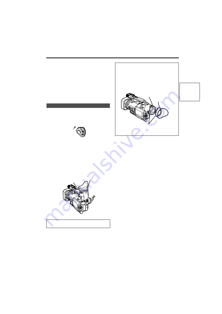
Viewfinder

This camera has two viewfinders; one is a miniature 
LCD in the viewfinder and the other is a retractable 
3.5-inch LCD.
Use the viewfinder that best suits the application 
and shooting conditions.

• The brightness and hue may differ between the 

images appearing on the viewfinder and LCD monitor 
and those displayed on a TV monitor.


To see how the final images will appear, check them 
on a TV monitor.

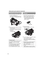
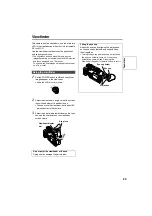
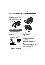
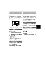
1

Set the POWER switch to ON and check that 
images appear in the viewfinder.
• Keep the LCD monitor closed.

2

Adjust the viewfinder’s angle so that the screen 
is positioned where it is easiest to see.
• You can move the view finder out to about 90° 

perpendicular to the camera.

3

Adjust the diopter adjustment lever so that you 
can see the characters on the viewfinder 
screen clearly.

Using the viewfinder

Do not point the viewfinder at the sun.

Doing so may damage the parts inside.

POWE

R

ON

OFF

Viewfinder diopter 
dial

Eye piece

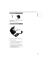
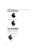
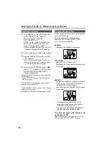
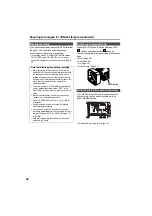
Fitting the eye cup

Attach the eye cup by aligning the projections 
on the eye cup holder and eye cup and fitting 
them together.

• Turning the eye cup after attaching it may cause 

the eye cup holder to come off. If the eyecup 
holder does come off, see “Cleaning the 
Viewfinder” (Page 83) for details on how to refit it.

Eye cup holder

Eye cup

Projection

Pr

epar

ati

ons

Содержание AG-DVX100B

Страница 1: ...ck Reference Preparation Description of parts Before use Operating Instructions Camera Recorder Model No AG P F0805S0 H VQT0U08 ENGLISH Before operating this product please read the instructions carefully and save this manual for future use ...

Страница 2: ...S SOCKET OUT LET SHALL BE INSTALLED NEAR THE EQUIPMENT AND SHALL BE EASILY ACCES SIBLE TO COMPLETELY DISCONNECT THIS EQUIP MENT FROM THE AC MAINS DISCONNECT THE POWER CORD PLUG FROM THE AC RECEPTACLE FCC Note This equipment has been tested and found to comply with the limits for a class A digital device pursuant to Part 15 of the FCC Rules These lim its are designed to provide reasonable protectio...

Страница 3: ...om overheating These openings must not be blocked or covered Never place the video unit on a bed sofa rug or other similar surface or near or over a radiator or heat register This video unit should not be placed in a built in installation such as a book case or rack unless proper ventilation is provided or the manufacturer s instructions have been adhered to 10 Power Sources This video unit should...

Страница 4: ...ectric shock Never spill liquid of any kind onto the video unit 18 Servicing Do not attempt to service this video unit yourself as opening or removing covers may expose you to dangerous voltage or other hazards Refer all servicing to qualified service personnel 19 Damage Requiring Service Unplug this video unit from the wall outlet and refer servicing to qual ified service personnel under the foll...

Страница 5: ...g 31 Preparation and inspections 31 Shooting in auto mode 31 Shooting techniques for different targets 32 Check what you have shot rec check 32 Finding specific scenes image search 32 Zoom 32 Low angle shooting 33 Self portrait shooting 33 Zebra pattern 33 Marker 33 ONE SHOT recording 34 Changing the image size 34 Optical Image Stabilizer 35 Using the USER buttons 35 Backlight compensation 35 Inde...

Страница 6: ... mode only 64 Warnings 64 Setting the DISPLAY items 65 Using the setup menus 66 Using the setup menus 66 Initializing the menu settings 67 Setup menu structure 68 Camera mode menu 68 VCR mode menu 68 Setup menu list 69 SCENE FILE screen 69 CAMERA SETUP screen 71 SW MODE screen 71 AUTO SW screen 72 PLAYBACK FUNCTIONS screen 73 RECORDING SETUP screen 74 AV IN OUT SETUP screen 75 DISPLAY SETUP screen...

Страница 7: ...o the shooting of certain material even if it is intended for private use Note concerning illustrations in these instructions Illustrations camera recorder menu screens etc in these operating instructions differ slightly from the actual camera recorder References References are shown as Page 10 Tapes you can use You can use tapes with this mark Accessories IMPORTANT Unauthorized recording of copyr...

Страница 8: ...ly affect the recorded images and or sound Do not allow any sand or dust to get into the camera recorder when using it at the beach and other similar places Sand and dust can damage the camera recorder and cassette Be especially careful when inserting or removing the cassettes AC adapter and battery If the battery is extremely hot or cold the CHARGE lamp will blink several times before charging st...

Страница 9: ... check that the battery and its terminals have not been damaged You can damage the camera and AC adapter if you try to use or recharge a damaged battery Liquid crystal displays Images or letters can get burned onto the screen of the LCD or viewfinder if they are displayed for a long time but you can fix this by leaving the camera off for several hours The liquid crystal parts are highly precise wi...

Страница 10: ...tically when the cassette cover is fully open The cassette holder will not open if the camera is not supplied with power AC adapter or battery 2 Insert the cassette as shown in the diagram Items to prepare AC adapter AC power supply cord DC cord Mini DV cassette tape Connect the AC power supply cord Connect the cords properly as shown in the figure above You cannot charge the battery when supplyin...

Страница 11: ...ra to the shooting standby mode Do not try to insert or eject the tape by just holding the cassette cover Insert and remove cassette tapes after putting the camera recorder down on a stable flat surface or hold it with both hands to keep it stable Do not force the cassette holder while it is moving Trying to do so could damage the camera Close the cassette cover only after the cassette holder is c...

Страница 12: ...only after the cassette holder is completely in position Do not close the cassette cover while the cassette holder is moving as this can damage the mechanism Check what you have shot rec check Power saving mode The camera recorder performs as follows when you pause or leave it in standby mode for about 5 minutes and do not perform any specified operations ON The camera recorder turns off automatic...

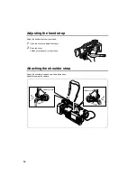
Страница 13: ...wfinder 3 While pressing the battery release pull the DC cord s battery connector towards you 4 Return the viewfinder to its original position Turn off the unit Disconnect the power cord Turn POWER to OFF and check that the POWER lamp CAM VCR has gone off before disconnecting the power cord POWER ON OFF CAMERA VCR Lock release Battery release Before use ...

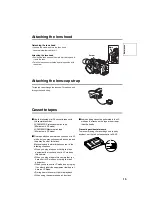
Страница 14: ...ap to suit your hand 1 Open the cover and adjust the length 2 Close the cover Make sure the cover is fully closed Attaching the shoulder strap Attach the shoulder strap and use it as a precaution against dropping the camera 20mm or more 20mm or more ...

Страница 15: ...if you shoot in LP mode but you may notice some block noise and there may be other limitations Block noise and feature limitations occur in the following situations When you play a tape on other digital video equipment that you have shot in LP mode on this camera When you play a tape in this camera that you have shot in LP mode on other digital video equipment When you have shot in LP mode and try...

Страница 16: ... FOCUS IRIS 3 5 mm mini jack Connect a remote control to remotely control focus and iris ZOOM S S 2 5 mm Super mini jack Connect a remote control to remotely control zoom and start stop 12 EJECT switch Page 10 13 Cassette section Page 10 a Cassette holder b Cassette cover 14 Tripod hole Page 9 15 Viewfinder diopter dial Page 23 16 Viewfinder Page 23 17 Power terminals Page 10 18 DC INPUT terminal ...

Страница 17: ...Pages 32 48 and 66 27 MENU button Page 66 28 AWB button Pages 41 and 42 29 FOCUS switch Page 38 30 PUSH AUTO button Page 38 31 USER buttons 1 to 3 Page 35 32 GAIN switch Page 43 33 WHITE BAL switch Page 41 34 IRIS dial Page 43 35 IRIS button Page 43 36 AUDIO control Page 44 37 CAMERA VCR button and lamp Page 48 38 Scene file dial Page 45 39 EVF DTL END SEARCH button Pages 24 and 51 AWB 20 22 24 26...

Страница 18: ... and 52 52 CH2 SELECT switch Page 44 53 MODE CHK button Page 65 54 ZEBRA button Page 33 55 OIS button Page 35 56 OPEN button Page 24 57 S VIDEO IN OUT terminal Page 55 58 DV terminal Page 36 59 VIDEO IN OUT terminal pin jack Page 55 60 Microphone shoe Page 53 61 Light shoe 62 Built in stereo microphone Page 44 63 Front tally lamp Page 82 64 Front remote control sensor 65 AUDIO IN OUT CH1 CH2 termi...

Страница 19: ...d volume control 14 START STOP button Same function as the START STOP button on the main unit 15 ZOOM VOL buttons Pages 32 and 49 16 VAR SEARCH button Page 51 17 MENU button Functions the same as the MENU button on the camera buttons Function the same as the t y e r buttons on the camera Remote control The following buttons are for functions that cannot be executed on the camera recorder PHOTO SHO...

Страница 20: ...rong camera recorder by mistake Setting Wireless remote control Press the STOP g and STILL ADV buttons at the same time to set the remote control unit for use with VCR1 Alternatively press the STOP g and STILL ADV buttons at the same time to set the remote control unit for use with VCR2 When the battery in the remote control unit is replaced the remote control unit is set for use with VCR1 Camera ...

Страница 21: ... 330 min Approx 360 or 300 min Keep metal objects such as necklaces and hairpins away from the battery Short circuiting may occur across the terminals causing the battery to heat up and you may seriously burn yourself if you touch the battery in this state The battery becomes hot while it is being used or charged The camera recorder itself also becomes hot during use The recordable time reduces if...

Страница 22: ...urn the viewfinder to its original position While pressing the battery release lift the battery out Attaching the battery Detaching the battery Turn POWER to OFF and check that the POWER lamp CAM VCR has gone off before detaching the battery Support the battery with your hand so that it does not fall 1 3 2 Battery release ...

Страница 23: ...le so that the screen is positioned where it is easiest to see You can move the view finder out to about 90 perpendicular to the camera 3 Adjust the diopter adjustment lever so that you can see the characters on the viewfinder screen clearly Using the viewfinder Do not point the viewfinder at the sun Doing so may damage the parts inside POWER ON OFF Viewfinder diopter dial Eye piece Fitting the ey...

Страница 24: ...he images you see in the viewfinder or on the LCD makes it easier to focus Emphasizing the outlines does not effect the images you shoot 1 In CAMERA mode press EVF DTL END SEARCH EVF DTL ON appears on the screen for about 2 seconds Press EVF DTL END SEARCH again to return to the original display EVF DTL OFF appears on the screen for about 2 seconds Using the LCD Ensure the LCD is fully closed Both...

Страница 25: ...the viewfinder s display You can change the LCD s displays in the same way EVF SET EVF CONTRAST EVF BRIGHTNESS EVF COLOR LEVEL PUSH MENU TO RETURN _ _ _ EVF SET EVF CONTRAST EVF BRIGHTNESS EVF COLOR LEVEL PUSH MENU TO RETURN _ _ _ You can return the settings for EVF SET and LCD SET to the factory settings by selecting the item and pressing COUNTER RESET if it is possible to change the item at that...

Страница 26: ...o DEC 6 Set DAY HOUR and MIN using the method shown in steps 4 and 5 This is a 24 hour clock 7 Press MENU three times to exit the menus Setting the calendar POWER ON OFF CLOCK SET PUSH MENU TO RETURN YEAR DAY MONTH HOUR MIN APR 7 24 13 2005 SEL PUSH REW FF PUSH PLAY STOP CLOCK SET PUSH MENU TO RETURN YEAR DAY MONTH HOUR MIN APR 7 24 13 2005 SEL PUSH REW FF PUSH PLAY STOP The clock can vary in accu...

Страница 27: ... menu buttons on the remote control Page 19 3 Move the OPERATION lever r to select UB PRESET 4 Press the OPERATION lever h or move it y move it r to select YES and press h again 5 The following screen appears so use the OPERATION lever to set the user information Move the OPERATION lever e or r to select the characters for the user information You can use numbers from 0 to 9 and letters from A to ...

Страница 28: ...owing time code related items Page 74 TC MODE TCG FIRST REC TC TC PRESET 1394 TC REGEN appears when in VCR mode In VCR mode and 1394 TC REGEN is ON you cannot change the items shown above You can reset user information to nothing by pressing COUNTER RESET OSD COUNTER RESET TITLE VOL MULTI P IN P REC A DUB PLAY REW FF ZOOM DATE TIME PHOTO SHOT START STOP Camera or Remote control MENU UB PRESET PRES...

Страница 29: ...xt digit Specifying the time code TC PRESET POWER ON OFF RECORDING SETUP PUSH MENU TO RETURN MIC ALC AUDIO REC MIC GAIN2 MIC GAIN1 50B ON 48K 16bit SP 50B REC SPEED TC MODE FIRST REC TC TCG REC RUN DF TC PRESET RECORDING SETUP PUSH MENU TO RETURN UB PRESET UB MODE REC TIME ONE SHOT REC OFF 0 5S USER YES TC PRESET RECORDING SETUP PUSH MENU TO RETURN UB PRESET UB MODE REC TIME ONE SHOT REC OFF 0 5S ...

Страница 30: ...nished setting the time code 7 The following screen appears so move the OPERATION lever e to select YES 8 Press the OPERATION lever h 9 Press MENU twice to exit the menus MENU TC PRESET PRESET OK NO PUSH STILL YES ___ TC PRESET PRESET OK NO PUSH STILL YES ___ MENU ...

Страница 31: ...data Page 26 Check that the date and time have been set correctly Check that the time code and user information have been set correctly g Audio input Page 44 Check that CH1 CH2 SELECT switch is in the correct position g Other equipment Page 53 Check that any equipment you have connected to the camera is working correctly Check that connections are complete and correct 1 Set the POWER switch to ON ...

Страница 32: ... x zoom Zoom with the zoom button or the zoom ring Zoom button Set the ZOOM switch to SERVO so that you can use the motor driven zoom T Zoom in W Zoom out Gently press the zoom button on the viewfinder to zoom slowly firmly press to zoom faster You can change the zoom speed on the handle zoom button by selecting one of three speeds with the HANDLE ZOOM switch Set HANDLE ZOOM switch speeds by going...

Страница 33: ...tern Very bright Reflecting parts You can remove most overexposed parts by adjusting the iris and shutter speed in the manual mode to remove the areas with zebra patterns The display changes as follows each time you press the ZEBRA button In the setup menus DISPLAY SETUP screen ZEBRA DETECT 1 and ZEBRA DETECT 2 set the brightness for the zebra patterns Page 76 The zebra pattern you have set appear...

Страница 34: ... setting switches to OFF when you turn the camera off To end ONE SHOT recording do one of the following 1 Switch the camera off 2 Change the ONE SHOT REC setting back to OFF You can change the aspect ratio of the images you record with this camera Select the aspect ratio in the setup menus CAMERA SETUP screen ASPECT CONV For menu operation Page 66 NORMAL Recorded in the regular 4 3 aspect ratio LE...

Страница 35: ...klight compensation adjusts the iris so the subject doesn t come out dark Press the same USER button to turn the feature off Press the USER button you have allocated to the INDEX feature during shooting and an index signal is recorded to the tape If you press the button while in shooting standby mode you also activate index standby mode When you start shooting or recording an index signal is recor...

Страница 36: ...nu settings are retained even if you turn the power off So if you use the camera recorder with the settings for backup recording still in effect images on tapes in any unit that connected may be overwritten After backup recording check the menu item settings before you operate the camera recorder If you use another AG DVX100B as the external unit for backup recording select OFF for DV CONTROL on t...

Страница 37: ... different frames which can cause a drop in picture quality With the 24P advanced method however frames BoCe and FoGe are cut out leading to a reduction in image quality loss If you also use a system compatible with the advanced method editing will also yield better quality images than those shot in the normal 24P mode If you are not going to do your editing on such a system use the normal 24P met...

Страница 38: ...automatically moves back to M MANUAL after you move it to Temporarily switching to auto focus Even if you have switched FOCUS to M MANUAL the camera will focus automatically while you press down PUSH AUTO Auto focus may not work properly if there is flickering Select a shutter speed suited to the ambient light Page 39 When you use auto focus in the progressive or slow shutter modes the focus assis...

Страница 39: ...with the power line frequency When this frequency is 50 Hz mutual interference will occur between the camera recorder s vertical sync frequency approx 60 Hz and the lighting frequency 50 Hz This means that the white balance may change periodically Before shooting in areas with artificial lighting or adjusting the white balance set the shutter speed as follows Progressive mode Normal shutter speeds...

Страница 40: ...with the SPEED SEL button Page 39 you cannot switch to slow shutter mode INVALID appears on the screen First press the SHUTTER button to return to normal OFF then switch to slow shutter mode Set the shutter speed of the synchro scan used when shooting a television or computer monitor in the setup menus CAMERA SETUP screen SYNCRO SCAN Page 71 Adjust the shutter speed to match the frequency of the t...

Страница 41: ...can be used instead Do not include bright spotlights in your shot 4 Set the WHITE BAL switch to A or B whichever one you want to save the adjustment in 5 Press the AWB button Adjustment takes a few seconds The following messages appear on the screen An error message appears on the screen when white balance adjustment is not possible White balance cannot be adjusted automatically if the Auto Tracki...

Страница 42: ...nd hold the AWB button to adjust the black balance As the white balance is adjusted first when you press the AWB button make the necessary preparations for this You cannot adjust the black balance while you are shooting You can allocate the ATW feature to one of the positions on the WHITE BAL switch A B or PRST Allocate it by going to the setup menus SW MODE screen ATW Page 71 The ATW feature is s...

Страница 43: ...de press the AUTO button to switch to the manual mode goes out 2 Switch the gain with the GAIN switch L Set here under normal conditions 0 dB M Increase the gain of the image amplifier The default value is 6 dB H Increase the gain of the image amplifier The default value is 12 dB Change the gain values of M and H in the setup menus SW MODE screen MID GAIN and HIGH GAIN Page 71 Use the ND FILTER Sw...

Страница 44: ... the setting at ON 4 Use the CH1 SELECT switch to select the input signal to be recorded to audio channel 1 INT L Audio from the built in microphone Lch is recorded to audio channel 1 INPUT 1 Audio from a device connected to INPUT 1 terminal is recorded to channel 1 INPUT 2 Audio from a device connected to INPUT 2 terminal is recorded to channel 1 5 Use the CH2 SELECT switch to select the input si...

Страница 45: ...e POWER switch to ON 2 Turn the scene file dial then select the scene file to be changed 3 In the setup menus select the SCENE FILE screen For menu operation Page 66 You can also use the menu buttons on the remote control Page 19 4 Move the OPERATION lever r to select NAME EDIT 5 Press the OPERATION lever h or move it y then move it r to select YES F1 SCENE File suitable for normal shooting F2 SCE...

Страница 46: ...and the changes to the scene file are complete 13 Press MENU three times to exit the menus NAME EDIT PUSH MENU TO RETURN SW POSITION F1 SEL PUSH PLAY PUSH STOP PUSH REW FF SCENE F1 PUSH MENU TO RETURN GAMMA SKIN TONE DTL V DETAIL FREQ KNEE MATRIX PROGRESSIVE NAME EDIT SAVE INIT NORMAL AUTO NORMAL OFF OFF SCENE F1 PUSH MENU TO RETURN GAMMA SKIN TONE DTL V DETAIL FREQ KNEE MATRIX PROGRESSIVE NAME ED...

Страница 47: ... set FILE TRANS to YES 7 The following screen appears so move the OPERATION lever r select the data for transfer and press the OPERATION lever h 8 The following screen appears so move the OPERATION lever e to select YES and press the OPERATION lever h File transfer starts FILE TRANS appears on the screen of camera 1 when the transfer is complete FILE RECEIVE OK PLEASE POWER OFF appears on the scre...

Страница 48: ...rward the tape During play move the lever y to play the tape at 10x speed While the tape is in the stop mode turn the lever in the direction t to rewind the tape During play move the lever t to rewind the tape at 10x speed Turn the lever in the direction g to stop the tape While the tape is playing back press this lever to set the camera recorder to the playback pause mode INDEX STOP INDEX STILL A...

Страница 49: ...ge 55 2 Start playback To show the information that appears on the viewfinder and LCD press the OSD button on the remote control Press the OSD button again to clear the display Press the DATE TIME button on the remote control to show the date and time of shooting on the screen The display changes as follows each time you press the button Adjusting the volume Viewing images on a television AUDIO MO...

Страница 50: ...can be performed using the supplied wireless remote control unit 1 During play press the INDEX buttons i or u The tape is cued at the next scene after showing S1 on the screen Each time you press the INDEX button thereafter S2 and then S3 are displayed and the tape is cued up to the second and subsequent scenes When the tape is cued up playback starts from that section Up to nine scenes before or ...

Страница 51: ... END SEARCH button in the VCR mode The unrecorded parts are found and a still picture that is about a second ahead is displayed When in the camera mode press and hold the EVF DTL END SEARCH button for at least a second A blank portion of the tape is found and a still picture that is about a second ahead is displayed while the camera is in recording standby mode If you change the tapes the camera w...

Страница 52: ...chronize the time codes of your cameras when using more than one for a shoot The camera used for synchronization is the MASTER and the camera being synchronized is the SLAVE 1 Connect a second camera with a DV IEEE1394 cable and turn both cameras off For connection Page 54 2 Put the MASTER camera in CAMERA mode and output a video signal from the DV IEEE1394 terminal Do the remaining steps on the S...

Страница 53: ...crophone to the microphone shoe use the supplied microphone holder and microphone holder adapter Headphones External microphone PHONES Microphone holder Microphone holder Adapter 12 mm 6 mm Stereo Microphone optional AG MC100G INPUT1 or INPUT2 Playback Editing ...

Страница 54: ...side the unit and cause malfunctioning Furthermore connect the DV IEEE1394 cable to the unit which uses a 6 pin type DV connector first 1 2 When recording signals from an external unit first check that video signals are supplied While signals from an external unit are being recorded do not stop output on the external unit side or disconnect any of cables This may lead to a failure to recognize the...

Страница 55: ...dio signals cannot be recorded unless video signals are input to the S VIDEO IN OUT connector and or VIDEO IN OUT jack Television Video deck DV IN OUT VIDEO IN OUT CH1 CH2 AUDIO IN OUT S VIDEO DV IN OUT VIDEO IN OUT CH1 CH2 AUDIO IN OUT S VIDEO AV cable optional Red CH2 Rch audio White CH1 Lch audio Yellow Video S video cable optional AV cable optional Red CH2 Rch audio White CH1 Lch audio Yellow ...

Страница 56: ... the setup menus select an audio recording system in the AV IN OUT SETUP screen A DUB INPUT For menu operation Page 66 You can also use the menu buttons on the remote control Page 19 MIC The sound of the built in microphone or the external unit connected to INPUT 1 2 connector is recorded Select by CH1 SELECT switch and CH2 SELECT switch A_IN The sound of audio component connected to 1AUDIO IN OUT...

Страница 57: ...during shooting and that you have dubbed are played back Performing audio dubbing as you listen You can monitor the sound by setting ST2 If you use headphones when performing audio dubbing on a recording using microphone input you can listen to the sound being dubbed When you perform audio dubbing using line input from the audio component connected to the AUDIO IN OUT jack you can listen to the so...

Страница 58: ...he shooting standby mode 5 Move the OPERATION lever g to stop recording 6 Stop playback on the external unit Analog digital AD conversion You can use this unit to convert analog to digital signals In the setup menus AV IN OUT SETUP screen set DV OUT to ON Page 75 This enables you to output digital images which were input as analog signals from an external unit through this unit s DV connector to a...

Страница 59: ...ect this unit to a video deck Page 55 2 Press the CAMERA VCR button and switch to the VCR mode 3 Move the OPERATION lever q to start play on this unit 4 Start recording on the video deck 5 Stop recording on the video deck 6 Move the OPERATION lever g to stop play Analog output CAMERA VCR Editing ...

Страница 60: ...ooting standby mode Each time you press the OPERATION lever h the unit switches between shooting and the shooting standby mode 5 Stop recording in the recorder If you are using this unit move the operation lever g 6 Stop playback on the other unit If you are using this unit move the operation lever g Digital input output CAMERA VCR COUNTER RESET TITLE STILL ADV PAUSE STILL ADV INDEX VOL STOP INDEX...

Страница 61: ...ilizer display Appears when the Optical Image Stabilizer is ON 4 Recording time mode SP LP SP Standard mode LP Extended mode 5 Progressive mode Frame rate information during shooting in the progressive mode is displayed here 6 Squeeze information Appears when in the setup menus CAMERA SETUP screen ASPECT CONV you have selected SQUEEZE Page 71 or when playing back images recorded in the squeeze mod...

Страница 62: ...tor volume level meter Press the AUDIO MON VAR button to display the level meter showing the volume level of the sound that is output from the internal speaker and PHONES jack 19 Calendar 20 INDEX record display When the USER button allocated the Index function in advance is pressed during the recording it will light when recording the index signal When you press the USER button before recording i...

Страница 63: ... sec FR 24P 24P progressive mode 24 frames sec FR 24PA 24P advanced mode When in FR24P and FR 24PA mode the sequence information of the frame conversion at the final place 31 Operational state display REC Recording Recording during self portrait shooting PAUSE Recording pause h Recording standby during self portrait recording Play pause STNDBY Standby the cylinder head is stopped A DUB Standby for...

Страница 64: ...the middle of the screen UNPLAYABLE TAPE OTHER FORMAT Can not playback because of the different tape format COPY INHIBITED Can not record correctly because of the input signal copy guarded UNABLE TO A DUB LP RECORDED Can not perform dubbing because the tape was recorded with LP mode INCOMPATIBLE TAPE Can not use because the tape is not the standard for this unit e g a tape for saving data EXTERNAL...

Страница 65: ... x 4 Progressive display 3 3 x x 5 Squeeze record display 3 3 3 x 7 Displaying the function allocated to the USER button 3 x x x 8 Auto IRIS control display 3 3 3 x 9 Shutter speed display 3 3 3 x 10 Microphone level auto control display 3 3 x x 11 Audio sampling frequency display 3 3 x camera 3 VCR x 13 Audio level meter display 3 14 Recommended ND filter display 3 3 3 x 15 Remaining tape display...

Страница 66: ...ATION lever e or r to highlight the item you want to change 3 Press the OPERATION lever h or move it y to display the items 4 Move the OPERATION lever e or r to highlight the item you want to change Using the setup menus MENU CAMERA MENU 3 SW MODE 4 AUTO SW 5 RECORDING SETUP 6 DISPLAY SETUP 7 OTHER FUNCTIONS 1 SCENE FILE 2 CAMERA SETUP PUSH MENU TO EXIT VCR FUNCTIONS 3 AV IN OUT SETUP 4 DISPLAY SE...

Страница 67: ... screen The setup menus are divided into user files and scene files You can initialize these separately To initialize the user file all items except the scene files In the OTHER FUNCTIONS screen USER FILE select INITIAL The settings for the current user file are returned to the factory settings Page 78 To initialize the scene files From the 6 scene files select the one you want to initialize with ...

Страница 68: ...O OUT OSD LCD BACKLIGHT LCD SET EVF SET SELFSHOOT EVF MODE EVF COLOR DISPLAY ASPECT DETAIL LEVEL V DETAIL LEVEL DETAIL CORING CHROMA LEVEL CHROMA PHASE COLOR TEMP MASTER PED A IRIS LEVEL GAMMA KNEE MATRIX SKIN TONE DTL V DETAIL FREQ PROGRESSIVE Pages 69 and 70 Page 71 Pages 71 and 72 Page 72 Pages 74 and 75 Page 76 Pages 77 and 78 RECORDING SETUP REC SPEED AUDIO REC TCG FIRST REC TC TC PRESET 1394...

Страница 69: ... it staid image The contrast become sharp NORMAL Makes standard images HIGH Using the gamma curve which the slope of low brightness is modest spreads out the tone of dark parts and makes it bright image The contrast become soft B PRESS Makes the contrast sharper than LOW CINELIKE Uses the gamma curve to complete the cine line image Images have less noise than CINELIKE_D CINELIKE_D Dynamic range is...

Страница 70: ...nd are played on a monitoring television 60i interlace you will feel flickers caused on horizontal lines and almost horizontal oblique lines When you play images under the progressive mode set the detail as THIN or MID This gives you higher resolution images than setting the detail as THICK Item Display mode Description of settings PROGRESSIVE camera Sets the shooting in progressive mode OFF Selec...

Страница 71: ...d to the M position of GAIN switch 0dB 3dB 6dB 9dB 12dB HIGH GAIN camera Sets the gain value which is to be allocated to the H position of GAIN switch 0dB 3dB 6dB 9dB 12dB ATW camera Sets the operation of the ATW Auto Tracking White function which is to be allocated to the WHITE BAL switch OFF Disables the ATW function However if the ATW function is set to the AUTO button or USER button the operat...

Страница 72: ...e USER3 button For further details refer to USER1 above INDEX AUTO SW screen Item Display mode Description of settings A IRIS camera ON Performs auto iris control when in auto mode The IRIS button is disabled OFF Disables the auto iris control when in auto mode This performs the iris control selected with the IRIS button AGC camera Sets the Auto Gain Control function for when the A IRIS option is ...

Страница 73: ... CH1 signals CH1 track CH3 track CH2 signals CH2 track CH4 track Note When the sound is recorded in the 48K 16bit audio mode CH3 and CH4 do not exist so the following is always the case CH1 signals CH1 track CH2 signals CH2 track Item Display mode Description of settings AUDIO OUT VCR Sets the audio signals to be output from the AUDIO IN OUT pin jack when the tape is played back CH1 CH2 CH1 output...

Страница 74: ...ode The non drop frame mode will be used when you are shooting in a progressive mode 24P or 24P ADV Item Display mode Description of settings TCG camera VCR Use this to set the mode in which to advance the time code FREE RUN The time code advances regardless of the operation mode REC RUN The time code advances only when recording FIRST REC TC camera VCR Select the time code to be recorded when you...

Страница 75: ...agement data Frame updates REC START STOP data a b c d Item Display mode Description of settings UB PRESET camera VCR Set user information Make sure you have set USER in UB MODE ONE SHOT REC camera Set ONE SHOT recording mode Page 34 ON OFF REC TIME camera Sets the length of time for ONE SHOT recording Page 34 0 5s 0 5 seconds 1s 1 0 second 1 5s 1 5 seconds 2s 2 0 seconds DV IN PRESET VCR Synchron...

Страница 76: ... remaining tape and battery charge ON OFF OTHER DIS PLAY camera VCR Select how much information to dis play Page 65 OFF PARTIAL ALL Item Display mode Description of settings CAMERA DATA VCR Select ON to show the camera settings such as image stabilizer F number and gain value during tape playback OFF ON LCD BACK LIGHT camera VCR Adjusts the backlight of the LCD moni tor Select HIGH for a brighter ...

Страница 77: ...ton works as a REC REC STOP button Note If the backup unit does not have a rec pause function select STOP END SEARCH camera VCR Sets the operation to be performed when a blank search is conducted Page 51 BLANK REC END Item Display mode Description of settings REC LAMP camera Sets lighting of the tally lamp OFF Tally lamp does not light FRONT Front tally lamp microphone side lights REAR Rear tally ...

Страница 78: ...selected ON for BEEP SOUND Use this when you are shooting in the 24P mode or any other time that sound delay becomes noticeable USER FILE camera VCR LOAD The previous scene file settings are loaded SAVE The changed user file settings are saved INITIAL The user file settings are returned to the factory settings After LOAD or INITIAL switch camera recorder OFF and then back ON to ensure that the set...

Страница 79: ...arging until the AC adapter s CHARGE lamp goes out Are you using the battery in a cold place The battery is affected by the ambient temperature Its operating time is reduced in low temperatures The battery may have reached the end of its service life The battery will become unchargeable The battery has a certain service life which varies depending on how the battery is used If the battery operates...

Страница 80: ...n the head P 15 Something is wrong with the time code display The time code display may not register a regular count if a tape is played in the reverse slow mode This is normal The remaining tape display differs from the actual amount of tape remaining The remaining tape is not displayed accurately if you shoot continuously for periods of less than 30 seconds The display may show 2 to 3 minutes le...

Страница 81: ... you can remove the cassette without turning ON the POWER switch P 10 Cannot perform any operation other than removing the cassette Condensation may have formed If this happens the only operation that you will be able to perform is to remove the cassette Wait until the condensation has dried out When the cassette holder is closed immediately after sliding EJECT switch to open the cassette holder s...

Страница 82: ...display may not appear for 10 to 15 minutes after it has started to form inside In very cold areas the condensation may freeze If this happens it will take another two to three hours for it to thaw out Tally lamp The tally lamp can be made to light up during shooting by selecting ON as the REC LAMP set ting in the OTHER FUNCTIONS screen Page 77 When the camera recorder is in any of the following s...

Страница 83: ...When you can t clean a dirty video head with the cleaning tape it needs cleaning and repair at the dealer Please contact them Regular Maintenance For the superior picture quality we recommend replacing consumable parts such as a video head approximately every 2 000 hours of use However this estimated time varies greatly depending on the environment in which it is used such as temperature humidity ...

Страница 84: ...s rewind your tapes to the beginning before storing them They will become slack if left stopped part way through for six months or more the time frame depends on the storage conditions Make sure that all of your tapes are rewound to the beginning before storage Always put your tapes back into their original cases before storing them Dust direct sunlight ultraviolet rays or humidity may damage the ...

Страница 85: ...80 000 pixel offset system Lens LEICA DICOMAR Optical image stabilizer lens Motorized Manual selectable 10x zoom F1 6 f 4 5 to 45 mm 35 mm equivalent 32 5 to 325 mm Color separation optical system Prism system ND filter 1 8 1 64 Gain settings 0 3 6 9 12 18 dB 60i mode 0 3 6 9 12 dB progressive mode however set to 0dB when the slow shutter mode is used Shutter speed settings Regular shutter speed 6...

Страница 86: ...l input output compliant with IEEE 1394 standard INPUT 1 INPUT 2 XLR 3 pins x2 CH1 CH2 LINE MIC selectable high impedance LINE 0 dBu MIC 50 dBu 60 dBu selectable in menu DC INPUT 7 9 V PHONES 3 5 mm stereo mini jack 100 Ω CAM REMOTE Mini jack 3 5 mm diameter FOCUS IRIS Super mini jack 2 5 mm diameter ZOOM S S AC ADAPTER indicates safety information Weight 160 g 0 35 lb Dimensions W x H x D 70 mm x...

Страница 87: ...87 MEMO Reference ...
Страница 88: ...5200 WESTERN ZONE 3330 Cahuenga Blvd W Los Angeles CA 90068 323 436 3500 Government Marketing Department 52 West Gude Drive Rockville MD 20850 301 738 3840 Broadcast PARTS INFORMATION ORDERING 9 00 a m 5 00 p m EST 800 334 4881 24 Hr Fax 800 334 4880 Emergency after hour parts orders 800 334 4881 TECHNICAL SUPPORT Emergency 24 Hour Service 800 222 0741 Panasonic Canada Inc 5770 Ambler Drive Missis...

Отзывы: