Panametrics T17 Скачать руководство пользователя страница 58

Chapter 4. Inserting T17 Transducers into the Pipe

46

Model T17 Installation Guide

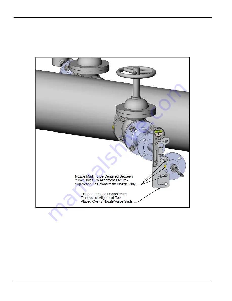
4.2.3 Aligning the Downstream Transducer (cont.)

8.

Place the alignment fixture over the two studs in the flange at the top of the barrel assembly, and rotate the 

barrel flange until the bubble aligns between the tick marks on the vial. Slowly press the flange toward the 

insertion mechanism flange until the gasket and raised faces of both flanges are mated. The studs should also 

engage the holes in the insertion mechanism flange. If desired, the barrel flange can be rotated slightly to 

maintain the bubble alignment on the gauge.

9.

Remove the fixture and install the remaining studs, washers, and nuts. Tighten them to the correct torque.

10.

Place a tag on the isolation valve stating the following:

DO NOT OPERATE (CLOSE) WHEN

TRANSDUCER IS INSERTED INTO PIPE.
11.

Refer to the flowmeter 

Startup Guide

 to make the transducer electrical connections.

Содержание T17

Страница 1: ...panametrics com Flow 916 128 C August 2021 Model T17 Ultrasonic Flow Transducer Installation Guide...

Страница 2: ......

Страница 3: ...ntains one or more registered trademarks of Baker Hughes Company and its subsidiaries in one or more countries All third party product and company names are trademarks of their respective holders Mode...

Страница 4: ...ii no content intended for this page...

Страница 5: ...followed carefully WARNING This symbol indicates a risk of potential serious personal injury unless these instructions are followed carefully WARNING It is the responsibility of the user to make sure...

Страница 6: ...ipment WEEE take back initiative directive 2012 19 EU The equipment that you bought has required the extraction and use of natural resources for its production It may contain hazardous substances that...

Страница 7: ...Model T17 Installation Guide v Chapter...

Страница 8: ...Chapter vi Model T17 Installation Guide no content intended for this page...

Страница 9: ...rking the First Nozzle Location Non Diametrical Mid Radius 18 2 3 3 Determining and Marking the Second Nozzle Location Non Diametrical Mid Radius 22 2 3 4 Installing the First Welding Boss Non Diametr...

Страница 10: ...Contents viii Model T17 Installation Guide...

Страница 11: ...Model T17 Installation Guide ix Contents...

Страница 12: ...Contents x Model T17 Installation Guide...

Страница 13: ...n on pipes ranging from 4 to 12 in 100 to 300 mm or for using the BIAS 90 configuration please see the Panametrics 916 117 Installation Guide 1 2 Transducer Construction Each T17 transducer assembly s...

Страница 14: ...tional Metal Engineering PTE Limited IME Type 8080 8075 8066 or 7080 certified under SIRA 07ATEX1331U and IECEx SIR 07 0111U or equivalent that complies with EN 60079 0 2012 IEC 60079 0 2011 and EN 60...

Страница 15: ...ations This section describes how to install nozzles in the different available configurations Standard flow range operation of 0 1 to 328 f s 0 03 to 100 m s This configuration uses two 180 head T17...

Страница 16: ...Installation Guide Selecting and marking the first nozzle location Determining and marking the second nozzle location Installing the first welding boss Installing the first nozzle Installing the secon...

Страница 17: ...igure 4 below to help identify each component IMPORTANT You will need to supply eight 5 8 studs with two nuts each for 3 150 flanges or 3 4 studs with two nuts each for 3 300 flanges Figure 4 Componen...

Страница 18: ...as possible to the horizontal plane i e 3 o clock and 9 o clock positions for horizontal pipe Note If you cannot find a proper location please consult with Panametrics Flow Application engineering CAU...

Страница 19: ...zle Location Diametrical cont 3 At the 3 o clock position center punch the pipe to mark the position for the center of the first nozzle 4 Spray this area with a marking dye product Using a metal edge...

Страница 20: ...D times the tangent of the installation angle 2 Due to the possible variation in outside diameter of the pipe measure the outside diameter of the pipe at four location between the nozzle centers Calcu...

Страница 21: ...first nozzle location Make sure the strip overlaps squarely around the pipe and mark the overlap position of the strip This equals the circumference of the pipe 5 Remove the strip of film and fold it...

Страница 22: ...sure you wrap the strip of film squarely around the pipe 8 The new position of the center of the second nozzle is now identified as the intersection of the fold line and the second edge of the strip...

Страница 23: ...tside diameter 1 660 in Table 1 below shows values of X for various pipe sizes 2 Scribe the oblique center line on the pipe at the prescribed distance from the true center line The oblique center line...

Страница 24: ...ake sure you orient the boss as shown below 4 Clamp the boss in place using a pipe strap or equivalent so that it cannot move during tack welding 5 Check the boss alignment then tack weld the carbon s...

Страница 25: ...using the jig and 1 in threaded rod provided prior to welding the nozzle 1 Screw the threaded rod into boss that is welded onto the pipe If necessary remove the washer and nut from the threaded rod 2...

Страница 26: ...d the nozzle must be removed and ground appropriately to provide the required clearance If the root gap is larger than the 0 094 in 2 4 mm dimension then suitably sized washers may be inserted between...

Страница 27: ...zle Diametrical Install the second welding boss and nozzle at the required position as described in Installing the First Welding Boss Diametrical on page 11 and Installing the First Nozzle Diametrical...

Страница 28: ...rocedure However an isolation valve is not necessary during the process The hot tapping medium can be applied directly to the nozzle Isolation valves will be added after the tapping is complete 2 3 No...

Страница 29: ...help identify each component IMPORTANT You will need to supply eight 5 8 studs with two nuts each for 2 150 flanges 2 300 flange or 3 150 flanges or 3 4 studs with two nuts each for 3 300 flanges Fig...

Страница 30: ...zzles on a chord as near as possible to the horizontal plane for horizontal pipe Note If you cannot find a proper location please consult with Panametrics Flow Application engineering CAUTION Correct...

Страница 31: ...irst Nozzle Location Non Diametrical Mid Radius cont 3 Locate the top of the pipe and put a center punch mark there as a reference mark 4 Calculate the position for the center of the first nozzle wher...

Страница 32: ...lling Pipe Nozzles 20 Model T17 Installation Guide 2 3 2 Selecting and Marking the First Nozzle Location Non Diametrical Mid Radius cont S 2 Xo AS 2 D 2 B D 2W 2 D 2 D 2W 2 CHORD LOC W B Xo Yo 2nd Noz...

Страница 33: ...404 46 mm 32 in 650mm 32 in 16 971 in 431 06 mm 34 in 34 in 18 018 in 457 66 mm 36 in 900mm 36 in 19 065 in 484 26 mm 38 in 38 in 20 113 in 510 86 mm 40 in 1000mm 40 in 21 160 in 537 46 mm 42 in 1050m...

Страница 34: ...he pipe For installation other than 45 the distance is equal to S times the tangent of the installation angle Steps 2 to 7 on the following pages are for the second nozzle located at 45 from the first...

Страница 35: ...n the nozzle centers Calculate the average outside diameter based on these measurements 3 Using a roll of polyester film or equivalent cut a strip of film at the width and length as follows IMPORTANT...

Страница 36: ...ing the Second Nozzle Location Non Diametrical Mid Radius cont Then mark a line at a distance AS from the left edge where AS D x with D average outside diameter calculated in Step 2 ATAN X0 Y0 in radi...

Страница 37: ...cribe lines at the first nozzle location Make sure the strip overlaps squarely around the pipe and that the marked line on the film from step 3 is on the outside and is visible 5 The new position for...

Страница 38: ...Before welding the first boss you must add another scribe line known as the oblique center line The oblique center line compensates for the slope or oblique of the boss The oblique center line is off...

Страница 39: ...65 mm 34 in 34 00 in 0 497 in 12 62 mm 36 in 900 mm 36 00 in 0 496 in 12 59 mm 38 in 38 00 in 0 495 in 12 57 mm 40 in 1000 mm 40 00 in 0 494 in 12 55 mm 42 in 1050 mm 42 00 in 0 493 in 12 53 mm 44 in...

Страница 40: ...he oblique center line on the pipe Make sure you orient the boss as shown below 4 Clamp the boss in place using a pipe strap or equivalent so that it cannot move during tack welding 5 Check the boss a...

Страница 41: ...ion using the jig and 1 in threaded rod provided prior to welding the nozzle 1 Screw the threaded rod into a boss that is welded onto the pipe If necessary remove the washer and nut from the threaded...

Страница 42: ...s not exist all around the nozzle must be removed and ground appropriately to provide the required clearance If the root gap is larger than the 0 094 in 2 4 mm dimension then suitably sized washers ma...

Страница 43: ...talling the Second Welding Boss and Nozzle Non Diametrical Mid Radius Install the second welding boss and nozzle at the required position as described in Installing the First Welding Boss and Installi...

Страница 44: ...ll bit Then use a coupon retaining hole saw to cut a hole with a diameter of 2 50 in 63 5 mm minimum 2 3 8 Cold Tapping the Pipe The procedure for cold tapping a pipe is the same as the hot tapping pr...

Страница 45: ...solation valves on both nozzles 8 in face to face for 150 RF flanges or 11 125 in for 300 RF flanges with a gasket and 5 8 in for 150 rated flanges or 3 4 in for 300 rated flanges diameter studs and n...

Страница 46: ...Chapter 3 Installing an Isolation Valve 34 Model T17 Installation Guide...

Страница 47: ...solation valves mounted to nozzles in the meter body Inserting the transducers into the pipe consists of the following Preparing for Installation Mounting the Insertion Mechanism Inserting the Transdu...

Страница 48: ...t be mounted on the end of a transducer during shipment IMPORTANT For an extended range operation meter the upstream and downstream transducers are different and it is crucial to the meter operation t...

Страница 49: ...transducer to make sure the top Swagelok fitting is not loose IMPORTANT The stop ring at the end of the barrel is supposed to be loose DO NOT tighten the Swagelok fitting or you could change the tran...

Страница 50: ...ract the barrel from the packing gland so that the transducer head is recessed in the packing gland You will hear the stop ring click when the transducer is fully recessed 5 Visually inspect the mecha...

Страница 51: ...to the Pipe 4 2 2 Mounting the Insertion Mechanism cont 6 Lift the gasket and insert the packing tool into the packing nut Turning the packing tool clockwise tighten the packing material so that the b...

Страница 52: ...ional For Extended Velocity Range applications the system is not bi directional Note which valve is designated upstream and downstream on the pipe Identify the upstream and downstream insertion mechan...

Страница 53: ...17 Transducers into the Pipe 4 2 2 Mounting the Insertion Mechanism cont 10 Lift the insertion mechanism by the barrel and place the insertion mechanism on the isolation valve 11 Line up the flange ho...

Страница 54: ...42 Model T17 Installation Guide 4 2 2 Mounting the Insertion Mechanism cont 12 Using the packing tool tighten the packing nut again until the nut is recessed WARNING The packing material must be secu...

Страница 55: ...uld support the barrel and one person should operate the alignment fixture Note Although the images in this section do not show the gasket referenced in Preparing for Installation on page 35 that gask...

Страница 56: ...ed transducer head is pointing in the correct direction uses the alignment marks on the downstream nozzle and the downstream Barrel assembly see the figure below The alignment marking on the flange at...

Страница 57: ...nozzle studs so that the two studs straddling the centerline on the nozzle are inserted into the holes on the fixture of the corresponding flange size and rating 3 150 or 300 5 Adjust the leveling wh...

Страница 58: ...mechanism flange until the gasket and raised faces of both flanges are mated The studs should also engage the holes in the insertion mechanism flange If desired the barrel flange can be rotated slight...

Страница 59: ...aged After the fitting is torqued into place ensure that the BNC head of the transducer extends slightly past the ground screw bosses as shown in Figure 8 below Figure 8 Torquing Reducer into NPT Port...

Страница 60: ...the transducer and the cable gland assembled the junction box should now look like Figure 10 below Figure 10 Assembled Transducer and Cable Gland 5 First connect the right angle male BNC plug to the...

Страница 61: ...e BNC plug of the XAMP to the male BNC transducer head as shown in Figure 12 below Figure 12 Female Plug to Male BNC Head 7 Wrap the extra length of cable around the perimeter of the junction box such...

Страница 62: ...ey exit the epoxy to reduce stress and strain on the joint The XAMP should remain still and the cap of the junction box should rotate freely around the XAMP Figure 14 Junction Box Cap 9 Place the cove...

Страница 63: ...QUENCE STARTING WITH 0001 MARKINGS ARE ENGRAVED OR ETCHED 17 OBLIQUE 174 14 HYDROSTATIC OVERPRESSURE TEST 2000 PSI 3000 PSI 4500 PSI WITHOUT LEAKAGE OR RUPTURE EACH HELD FOR ONE MINUTE BEFORE FILLING...

Страница 64: ...Chapter 4 Inserting T17 Transducers into the Pipe 52 Model T17 Installation Guide...

Страница 65: ...e mounting bolts may be required if erratic flow rate measurements are observed If you suspect something is wrong with a transducer or need to replace a transducer use the removal procedure that follo...

Страница 66: ...sertion Mechanism cont 3 On the insertion mechanism remove the bolts that fasten the barrel flange to the packing gland flange 4 Retract the barrel from the packing gland until the transducer head is...

Страница 67: ...CLOSE THE ISOLATION VALVE 6 After closing the isolation valve remove the bolts that fasten the packing gland flange to the isolation valve flange and lift the insertion mechanism by the barrel to remo...

Страница 68: ...ism cont 7 Install a new flange gasket on the isolation valve Then fasten a blind flange onto the isolation valve with the bolts removed in the previous step 8 Disconnect the junction box on the end o...

Страница 69: ...n Mechanism Holder Ratings 150 300 Electrical Rating 200 V peak to peak 5 mA Operating Temperature 67 to 300 F 55 to 150 C Storage Temperature 67 to 300 F 55 to 150 C Operating Pressure 12 7 to 1500 p...

Страница 70: ...Chapter 6 Specifications 58 Model T17 Installation Guide...

Страница 71: ...pose and warranties arising from course of dealing or usage or trade Return Policy If a Panametrics Sensing instrument malfunctions within the warranty period the following procedure must be completed...

Страница 72: ...Warranty 60 Model T17 Installation Guide no content intended for this page...

Страница 73: ...dustrial Locations EN 61326 2 3 2006 EN 61010 1 2012 Overvoltage Category II Other standards used EN 50014 1997 A1 A2 EN 50018 2000 following the provisions of the 2004 108 EC EMC and 94 9 EC ATEX Dir...

Страница 74: ...2 Model T17 Installation Guide...

Страница 75: ......

Страница 76: ...and company names are trademarks of their respective holders 916 128 rev no Customer Support Centers U S A The Boston Center 1100 Technology Park Drive Billerica MA 01821 U S A Tel 800 833 9438 toll...

Отзывы: