Panametrics BWT System Скачать руководство пользователя страница 9

BWT™ System Installation Guide

1

Chapter 1. General Information

Chapter 1. General Information

1.1

Introduction

Installing the Bundle Waveguide Technology™ (BWT

TM) 

 System consists of creating a meter body, installing the 

transducer buffer, and then mounting transducers into the buffer. Panametrics offers a variety of buffers and meter 

bodies for liquid and gas applications. This section consists of general information for the following topics:

• Types of BWT buffers (see 

page 1)

• General guidelines for transducer position and location (see 

page 2)

• BWT meter body (see 

page 3)

• Handling and installing a meter body (see 

page 5)

• Welding requirements (see 

page 7)

• Meter body requirements when flushing (see 

page 7)

IMPORTANT:

If the BWT buffers and transducers are used in a PanaFlow HT system, you must follow all instructions in 

the PanaFlow HT User’s Manual (910-294U) and Safety Manual (917-025).

1.2

Types of BWT Buffers

Buffers are used to protect the BWT transducers from temperature extremes. Since they mount directly into the pipe 

coupling or nozzle, they also act as barriers against the process, making it possible for the transducers to be 

removed without interrupting the process or emptying the pipe.

IMPORTANT:

The buffers also ensure that the service temperature of the transducers remains at ambient.

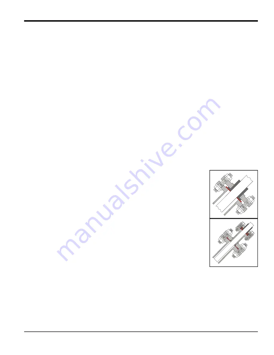
There are three BWT buffer types available for transducers for liquid and gas applications:

• Standard BWT Buffer (part number 

FTPA

) - is used for liquid and gas applications. The 

buffer has a flanged process connection and is available in two lengths: 

2 in.


(temperatures up to 600

o

F/315

o

C) and 

6 in.

 (temperatures up to 1,100

o

F/600

o

C).

• Acoustic Isolation BWT Buffer (part number 

FIPA

) - is used for gas applications at 

lower pressures. The buffer has a flanged isolation section that reduces acoustic 

short circuits. The outer buffer has a flanged process connection and is available in 

two lengths

2 in.

 (temperatures up to 600

o

F/315

o

C) and 

6 in.

 (temperatures up to 

1,100

o

F/600

o

C).

Содержание BWT System

Страница 1: ...panametrics com Flow 916 058 F July 2021 BWT System Installation Guide ...

Страница 2: ......

Страница 3: ...re registered trademarks of Baker Hughes Company and its subsidiaries in one or more countries All third party product and company names are trademarks of their respective holders Flow BWT System Bundle Waveguide Technology Flow Transducer Sys tem Installation Guide 916 058 F July 2021 ...

Страница 4: ...ii no content intended for this page ...

Страница 5: ...followed carefully WARNING This symbol indicates a risk of potential serious personal injury unless these instructions are followed carefully WARNING It is the responsibility of the user to make sure all local county state and national codes regulations rules and laws related to safety and safe operating conditions are met for each installation WARNING For installations in potentially hazardous ar...

Страница 6: ...quipment WEEE take back initiative directive 2012 19 EU The equipment that you bought has required the extraction and use of natural resources for its production It may contain hazardous substances that could impact health and the environment In order to avoid the dissemination of those substances in our environment and to diminish the pressure on the natural resources we encourage you to use the ...

Страница 7: ...ting the Junction Box 17 2 5 2 Inserting the BWT Transducer 18 2 5 3 Verifying the Installation 19 Chapter 3 Acoustic Isolation Installation FIPA Buffers 3 1 Introduction 21 3 2 Identifying and Checking the Components 21 3 3 Inserting the Acoustic Isolation FIPA Buffer 23 3 4 Torquing the Studs 27 3 5 Installing the BWT Transducer 30 3 5 1 Installing and Orienting the Junction Box 30 3 5 2 Inserti...

Страница 8: ...Contents BWT System Installation Guide ...

Страница 9: ...5 1 2 Types of BWT Buffers Buffers are used to protect the BWT transducers from temperature extremes Since they mount directly into the pipe coupling or nozzle they also act as barriers against the process making it possible for the transducers to be removed without interrupting the process or emptying the pipe IMPORTANT The buffers also ensure that the service temperature of the transducers remai...

Страница 10: ...rement The more straight run available the better Undisturbed flow means avoiding sources of turbulence such as valves flanges and elbows You should also avoid swirl cross flow and cavitation in liquids 2 It is important to locate the transducers on a horizontal plane This specifically applies to mounting transducers on a horizontal pipe One transducer cannot be on top of the pipe and one on the b...

Страница 11: ... or on a flowcell A flowcell is a precision manufactured section of matching pipe that contains the ports where the transducer buffers will be mounted This setup allows more accurate transducer alignment before mounting the meter body into the pipeline If requested a meter body can be calibrated prior to shipment All meter bodies are factory supplied 1 4 1 Single Traverse Meter Body A single trave...

Страница 12: ...ts of two transducers mounted on the pipe so that the signal traverses the fluid two times before reaching the other transducer see Figure 3 below Figure 3 Double Traverse Meter Body TOP L Projected distance of acoustical path in liquid P Distance that the signal travels through the liquid from one transducer to the other L P 45o 45o ...

Страница 13: ...to not disturb the buffers when unpacking 1 5 2 Installing a Meter Body Meter bodies can be either flanged or welded into the existing pipeline Use the following steps to position the meter body into the pipeline refer to Figure 4 on the next page 1 Find the tag plate with the words TOP and FLOW DIRECTION marked on it If the meter body is flanged two bolt holes should straddle the vertical centerl...

Страница 14: ...Chapter 1 General Information 6 BWT System Installation Guide Figure 4 Top View of a Flanged Meter Body Top End View centerline symmetrically Bolt holes straddle the Top View A A ...

Страница 15: ...body during flushing operations otherwise damage may occur for the following reasons Fast moving solid objects in the flowing medium could damage the buffer faces Flushing residue sediment could clog nozzles In the event that a dummy meter body is not available for flushing operations remove the buffers and plug the holes properly for the temperature and pressure used Blind flanges are typically u...

Страница 16: ...Chapter 1 General Information 8 BWT System Installation Guide no content intended for this page ...

Страница 17: ... component Note The list below is for a one path installation 2 FTPA buffers 2 BWT1 transducers 2 Kamprofile gaskets IMPORTANT Kamprofile gaskets must be used for two reasons they ensure a leak tight seal and they provide necessary acoustic isolation 2 Mating lap joint flanges 2 Junction boxes Preamplifiers required for gas flow applications may be mounted in transducer junction box 3M epoxy or eq...

Страница 18: ...ffers 10 BWT System Installation Guide Figure 5 Components for FTPA Buffer Figure 6 Gaskets BWT Transducer Junction Box FTPA Buffer Mating Lap Joint Flange Kamprofile with Metal Centering Ring Typical Kamprofile without Metal Centering Ring ...

Страница 19: ...sure you orient the flange as shown below 2 Check the raised face of the spool nozzle flange to make sure it is free from paint rust dirt corrosion and damage If necessary clean the raised faces with steel wool In addition clean the buffer flange if you are reusing an existing buffer 3 Inspect the gaskets supplied by Panametrics They must not be used warped pitted or scratched 4 Place one gasket o...

Страница 20: ...y 2 Insert the buffer assembly into the nozzle 3 Apply Copperslip Molykote or equivalent anti seize compound on the first several threads at both ends of each stud 4 Insert one of the studs through the flanges Make sure the stamped quality rating on the stud e g B7 is facing away from the meter body Hand tighten a washer and nut on each end of the stud Make sure you leave an equal number of thread...

Страница 21: ...the middle of the lap joint flange Inspect 360 around the flanges to ensure equal spacing by sliding your fingers around the gap between the buffer flange and the nozzle flange 7 Then align the flanges as shown below IMPORTANT Make sure the gasket is in the center of the flanges Equal Amount of Threads Stud Quality Rating Side View Side View 1 1 2 2 3 3 4 4 5 6 7 8 4 Hole Flange 8 Hole Flange ...

Страница 22: ...til it is centered It is important to torque the studs properly for a good seal However do not over torque them or you will cause an acoustic short or change the transducer alignment Tighten and torque the studs in increments as described below 1 Check the flange and buffer alignment again Make sure the flanges are consistently parallel to each other 2 Using an adjustable wrench turn the first nut...

Страница 23: ...r studs Table 1 Final Torques Flange Size and Rating Stud Rating with 4 Studs Flange Stud Diameter in x Length in Torque in ft lb N m 316 Stainless Steel 1 1 2 ANSI 150 B8M C 1 1 2 x 3 1 4 56 76 1 1 2 ANSI 300 B8M C 1 3 4 x 4 3 4 82 111 1 1 2 ANSI 600 B8M C 1 3 4 x 4 3 4 82 111 1 1 2 ANSI 900 B8M C 1 1 x 6 107 145 1 1 2 ANSI 1500 B8M C 1 1 x 6 107 145 Carbon Steel 1 1 2 ANSI 150 B7 1 2 x 3 1 4 56 ...

Страница 24: ...the spacing between the flanges with the caliper on at least four equally spaced points The maximum tolerance is 0 2 mm difference between the four measured points If you cannot achieve a tolerance of 0 2 mm or less replace the gasket with a new gasket and repeat this entire procedure 10 Repeat the above steps for the remaining flanges 2 5 Installing the BWT Transducer Installing the BWT transduce...

Страница 25: ...ter it is installed 1 Screw the transducer into the junction box as shown below 2 Screw the transducer junction box assembly into the FTPA Buffer 3 Check the junction box orientation The junction box cover should be at a downward angle so that any liquid can drain out of the box If necessary adjust the junction box until the cover is angled downward 4 Remove the transducer junction box assembly 5 ...

Страница 26: ... below place a small droplet 2 mm in diameter of 3M Epoxy or equivalent on the center of the transducer face the picture below shows the transducer without the junction box 2 Screw the transducer junction box into the fitting at the end of the FTPA Buffer When you begin to feel some resistance stop turning the transducer and wait 5 seconds to give the couplant a chance to spread out IMPORTANT In t...

Страница 27: ...al to display the upstream and downstream transducer signal strength 3 Record this data in the Service Record in the appendix provided for this purpose in the flowmeter Service or User s Manual 4 Verify that the signal strength diagnostics readings are the same or better after 8 hours of operation This completes the installation of the FTPA buffers and transducers Refer to the flowmeter Startup Gu...

Страница 28: ...Chapter 2 Standard Installation FTPA Buffers 20 BWT System Installation Guide no content intended for this page ...

Страница 29: ... list below is for a one path installation Acoustic Isolation FIPA Buffers fully assembled 2 BWT1 transducers 2 Kamprofile gaskets IMPORTANT Kamprofile gaskets must be used for two reasons they ensure a leak tight seal and they provide necessary acoustic isolation 2 Junction boxes Preamplifiers required for gas flow applications may be mounted in transducer junction box 3M epoxy or equivalent for ...

Страница 30: ...WT System Installation Guide Figure 7 Components for Acoustic Isolation FIPA Buffer Figure 8 Gaskets BWT Transducer Acoustic Isolation FIPA Buffer fully assembled Junction Box Kamprofile with Metal Centering Ring Typical Kamprofile without Metal Centering Ring ...

Страница 31: ...ucer on page 30 1 Check the raised face of the spool nozzle flange to make sure it is free from paint rust dirt corrosion and damage If necessary clean the raised faces with steel wool In addition clean the buffer flange if you are reusing an existing buffer 2 Inspect the gaskets supplied by Panametrics They must not be used warped pitted or scratched 3 Place one gasket on the end of the buffer 4 ...

Страница 32: ...n the first several threads at both ends of each stud 7 Insert one of the studs through the flanges Make sure the stamped quality rating on the stud e g B7 is facing away from the meter body Hand tighten a washer and nut on each end of the stud Make sure you leave an equal number of threads exposed on each end of the stud Inspect Pipe Nozzle Top View Top View Nozzle Gasket Top View Buffer Gasket N...

Страница 33: ...order shown below but do not fully tighten the nuts yet CAUTION Do not adjust the studs on the FIPA isolation flange The isolation flange is already set to specification determined at the factory Equal Amount of Threads Stud Quality Rating Top View Top View Isolation Flange 1 1 2 2 3 3 4 4 5 6 7 8 4 Hole Flange 8 Hole Flange ...

Страница 34: ...uffer flange and the nozzle flange 10 Then align the flanges as shown below IMPORTANT Make sure the gasket is in the center of the flanges 11 Tighten the nuts on the studs further by hand to maintain the centering Visually verify that the buffer is centered in the lap joint flange If necessary adjust the buffer by hand until it is centered Good Bad End View End View Flange Proper Gasket Alignment ...

Страница 35: ...hem or you will cause an acoustic short or change the transducer alignment Tighten and torque the studs in increments as described below 1 Check the flange and buffer alignment again Make sure the flanges are consistently parallel to each other 2 Using an adjustable wrench turn the first nut turn Bad Alignment Unequal Distances Not Centered Top View Top View Proper Alignment Equal Distances Center...

Страница 36: ...e Size and Rating Stud Rating with 4 Studs Flange Stud Diameter in x Length in Torque in ft lb N m 316 Stainless Steel 1 1 2 ANSI 150 B8M C 1 1 2 x 3 1 4 56 76 1 1 2 ANSI 300 B8M C 1 3 4 x 4 3 4 82 111 1 1 2 ANSI 600 B8M C 1 3 4 x 4 3 4 82 111 1 1 2 ANSI 900 B8M C 1 1 x 6 107 145 1 1 2 ANSI 1500 B8M C 1 1 x 6 107 145 carbon steel 1 1 2 ANSI 150 B7 1 2 x 3 1 4 56 76 1 1 2 ANSI 300 B7 3 4 x 4 3 4 82...

Страница 37: ...1 8 turn at a time 8 Repeat Step 7 for each of the incremental torque settings 9 Check the flange alignment again to ensure that the flanges are parallel to each other Measure the spacing between the flanges with the caliper on at least four equally spaced points The maximum tolerance is 0 2 mm difference between the four measured points If you cannot achieve a tolerance of 0 2 mm or less replace ...

Страница 38: ...lling and Orienting the Junction Box Before placing the BWT transducer into the FIPA buffer permanently you must make sure the junction box will be properly oriented after it is installed 1 Screw the transducer into the junction box as shown below 2 Screw the transducer junction box assembly into the FIPA Buffer 3 Check the junction box orientation The junction box cover should be at a downward an...

Страница 39: ...s Note In gas applications the typical minimum pressure should be 5 barg 75 psig for the transducers to receive any signal A pressure higher than this minimum should result in a better signal to noise ratio 1 As shown below place a small droplet 2 mm in diameter of 3M Epoxy or equivalent on the center of the transducer face the picture below shows the transducer without the junction box 2 Screw th...

Страница 40: ...r flowmeter 6 After you install the FIPA Buffers and transducers you must allow the epoxy to cure for 8 hours However while the epoxy cures you should verify that the transducer and buffer are working properly see the next section below 7 Repeat steps 1 6 to install the other transducer CAUTION Do not place insulation on or around the transducer or junction box The transducer and junction box act ...

Страница 41: ...nd transducers Refer to the flowmeter Startup or User s Manual for instructions on obtaining flow rate measurements 3 6 Installing Additional Acoustic Isolation If your application requires additional acoustic isolation obtain the following items to perform the procedure 1 to 3 ring collets for 4 in pipes or larger Allen wrench After you have obtained the above items complete the following steps 1...

Страница 42: ...buffer as shown below 4 Repeat the above steps for the other transducer This completes the installation of the FIPA buffers and transducers Refer to the flowmeter Startup Guide or User s Manual for instructions on obtaining flow rate measurements Wrench Loosen Using Allen Front View Ring 1 in 25 mm Top View Collets ...

Страница 43: ...ypes of buffers enable you to install and remove transducers easily without interrupting the process or emptying the pipe Installing the BWT transducers into an FSPA or FWPA buffer requires three steps Installing the FSPA or FWPA buffer see page 36 Installing and orienting the transducer junction box see page 37 Note For gas flow applications a preamplifier is required In such applications the pre...

Страница 44: ...se Teflon tape thread sealant on the buffer threads and screw the buffer into the transducer port Hand tightening the NPT threads will seal the connection without torquing FWPA Socket Weld Mount Insert the buffer into the meter body transducer port and weld it to the port in accordance with all applicable safety codes and procedures WARNING Welding should be performed by qualified personnel only S...

Страница 45: ...e The figures below show the FSPA Buffer only as an example 1 Screw the transducer into the junction box as shown below 2 Screw the transducer junction box assembly into the FSPA FWPA buffer 3 Check the junction box orientation The junction box cover should be at a downward angle so that any liquid can drain out of the box If necessary adjust the junction box until the cover is angled downward 4 R...

Страница 46: ...ransducer without the junction box 2 Hand tighten transducer then torque it to a maximum of 15 ft lb 20 N m 3 Verify that the junction box is properly oriented as discussed in the previous section see page 37 4 To connect the required cables from the junction boxes to the electronics see the Startup or User s Manual that was supplied with your flowmeter WARNING Follow all applicable safety codes a...

Страница 47: ...User s Manual to display the upstream and downstream transducer signal strength 3 Record this data in the Service Record in the appendix provided for this purpose in the flowmeter Service or User s Manual 4 Verify that the signal strength diagnostics readings are the same or better after 8 hours of operation This completes the installation of the FSPA FWPA buffers and transducers Refer to the flow...

Страница 48: ...Chapter 4 Non Flanged Installation FSPA FWPA Buffers 40 BWT System Installation Guide no content intended for this page ...

Страница 49: ...nal Titanium FTPA FIPA short buffers only available to meet EN10243 1 B and or NACE requirements Pressure To maximum allowable flange operating pressure at temperature or 3480 psi 240 bar FTPA FIPA Short Buffers Fluid temperature 310 F to 600 F 190 C to 315 C Minimum pressure gas service typically 100 psi 6 9 bar depending on fluid density FTPA FIPA Extended Buffers Fluid temperature Liquids 310 F...

Страница 50: ...ns Explosion proof Class I Division 1 Groups C D Flameproof BWT II 2 G Ex d IIC T6 Gb KEMA 01ATEX2051 Ex d IIC T6 Gb IECEx KEM 09 0010 JB II 2 G Ex d IIC T6 Gb DEKRA 13ATEX0120X Ex d IIC T6 Gb IECEx DEK 13 0034X European Compliance Complies with directives 2004 108 EC EMC 2006 95 EC LVD Installation Category II Pollution Degree 2 94 9 EC ATEX and 97 23 EC PED for DN 25 Pipe Sizes 2 in to 30 in 50 ...

Страница 51: ...T System Installation Guide 43 Chapter 5 Specifications Note For gas flow applications a preamplifier is required In such systems the supplied preamplifiers may be mounted in the transducer junction boxes ...

Страница 52: ...Chapter 5 Specifications 44 BWT System Installation Guide no content intended for this page ...

Страница 53: ... and warranties arising from course of dealing or usage or trade Return Policy If a Panametrics instrument malfunctions within the warranty period the following procedure must be completed 1 Notify Panametrics giving full details of the problem and provide the model number and serial number of the instrument If the nature of the problem indicates the need for factory service PanametricsPanametrics...

Страница 54: ...46 BWT System Installation Guide no content intended for this page ...

Страница 55: ...he instructions contained in the manual The installation should comply with IEC EN 60079 14 To avoid an ignition hazard protect the transducer from impact or friction This is of particular importance when the material of construction is titanium The apparatus must be securely attached to the site of the flow measurement Before installation check that the transducer adapter and enclosure are firmly...

Страница 56: ...facturing site Baker Hughes EMEA Shannon Co Clare Ireland QAN License Number 0794 Notified Body for Quality Assurance Notification SGS Baseefa Notified Body Number 1180 Certificate Number KEMA 01ATEX2051 IECEx KEM 09 0010 Apparatus Markings see example below II 2 G Ex d IIC T6 Gb 40 C Tamb 70 C Max Process Temp Max Ambient Temp XAMP No XAMP Buffer Length Temp Class 70 C 40 C 60 C 0 2 6 10 T6 85 C ...

Страница 57: ......

Страница 58: ...duct and company names are trademarks of their respective holders 916 058 F Customer Support Centers U S A The Boston Center 1100 Technology Park Drive Billerica MA 01821 U S A Tel 800 833 9438 toll free 978 437 1000 E mail mstechsupport bakerhughes com Ireland Sensing House Shannon Free Zone East Shannon County Clare Ireland Tel 353 61 61470200 E mail mstechsupport bakerhughes com ...

Отзывы: