
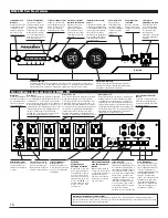

MAIN POWER 120 VAC/15A
GROUND
LUG
UNIVERSAL COAX PROTECTION
1 2 3
LAN 1
LINE IN
LAN 2
LINE IN EQUIP.
PHONE
LINE IN EQUIP.
15 AMP CIRCUIT BREAKER
BANK
1 & 2
ON
BANK 5
BANK 4
BANK 2
SUB /
AM
P
R
ECEIVER
HIGH CURRENT
SWITCHED DELAYED
DVD
C
D
PRE
AM
P
DI
G
IT
AL
RADIO
HD CABLE S
AT
H
D
TV /
MONI
TO
R
VCR /
AUX
DV
R
VOLTAGE
SENSE TRIGGER
OUTPUT INPUT
BANK 3
BANK 1
LINEAR FILTER
LINEAR FILTER
SWITCHED
SWITCHED
LINEAR FILTER
ALWAYS ON
LINEAR FILTER
(3-24 VDC)
ALWAYS ON
BANK 1 BANK 2 BANK 3 BANK 4 BANK 5
LINEAR LINEAR LINEAR LINEAR HIGH WIRING
FILTER FILTER FILTER FILTER CURRENT OK
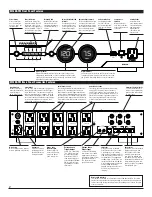
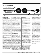
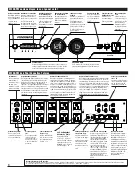
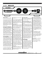
M5300-PM
METER LIGHTS
VOLTS
AMPS
Circuit Breaker
Automatically opens
when the current load
is greater than 15
Amps. Push to reset.
Convenience
LAN Port
Offers an Ethernet
pass-thru connection
between the front and
rear panel.
Power Indicators
Indicates the status of the
rear panel outlets. The LED
outlet bank icon will be lit
when the corresponding out-
lets are turned ON. They will
flash during the startup and
shutdown process.
Power Button
Press and hold for
one second to turn
Bank 3, 4, and 5 out-
lets ON or OFF.
Wiring OK LED
Normally On. Indicates
that the wall outlet is
properly grounded and
Line/Neutral polarity is
correct.
USB Charging Port
For charging portable
electronic devices
while protecting them
from unsafe voltages.
USB 5V.
Meter/Front Panel LED
Dimmer
Pushbutton control for
meter and front panel
LED brightness. Cycles
between four bright-
ness settings.
Gaming Outlet
Convenient front
panel outlet provides
surge protection for
gaming systems,
digital cameras,
camcorders, and
other devices.
Digital Voltmeter
Digital LED voltmeter indicates the incoming line voltage. If line
voltage drops below 90VAC, or if the line voltage exceeds 142VAC,
the display will turn off and the “unsafe voltage” indicator will flash
indicating an unsafe voltage condition.
Digital Ammeter
Shows the actual current draw (0-15A) of the connected
components system, giving a visual reference as to how
the system is functioning under a variety of conditions.
Note to CATV Installers:
This reminder is provided to call attention to Article 820-40 of the NEC. That article
provides specific guidelines for proper grounding. It specifies that the cable ground
shall be connected to the grounding system of the building and as close to the point
of entry as practical.
Unsafe Voltage Indicato
r
Located in the Voltmeter and
is normally off. Flashes red
to indicate that the incoming
line voltage is unsafe and the
unit has disconnected the
power to protect your equip-
ment.
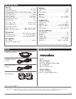
M5300-PM Back Panel Connection Features
M5300-PM Front Panel Features
Bank 1 and 2
Indicator Light
Normally ON, is lit
when there is power
present on Bank 1
and 2 receptacles.
Ground Lug
Provides a common
grounding point for
equipment with sep-
arate ground leads.
Main Power
Must be plugged into a properly
wired & grounded 3-wire outlet.
Universal TV Coaxial Jacks
3 pairs of bidirectional pro-
tection circuits optimized for
satellite, cable, and antenna
TV signal lines.
Phone Jacks
Protection circuits for standard
telephone or pay-per- view
lines. Phone circuit is auto-
resetting. Incoming phone
cord MUST be plugged into
the LINE jack. Patch cords to
the equipment (satellite receiv-
er, digital video recorder, tele-
phone, etc.) MUST be plugged
into the EQUIP jacks.
LAN Jacks
Protection circuits for 10/100
baseT Ethernet lines. For the LAN
2 protected jacks, the incoming
LAN line MUST be plugged into the
LINE jack and the patch cord to the
equipment MUST be plugged into
the EQUIP jack. For the LAN 1 pro-
tected jacks the incoming LAN line
must be plugged into the LINE jack
and the equipment must be
plugged into the jack on the front
panel. 8 wire protection, 52V
clamping.
Outlet Bank 5
Two switched, high-current outlets controlled by
the front panel Power Button or the DC Trigger
input. Bank 5 has a 5 second turn on delay and
turns off immediately upon shutdown. The High
Current outlets provide power from a low imped-
ance noise filtration circuit that does not limit the
current to your equipment. Its output is noise
isolated from all other outlet banks
Outlet Banks 3 and 4
Two switched outlets with linear filtration tech-
nology (LiFT) controlled by the front panel
Power Button or the DC Trigger input. Banks 3
& 4 will turn on immediately and turn off after a
10 second delay. LiFT EMI/RFI noise filtration is
provided by a two-stage balanced Pi filter which
also provides noise isolation from all other out-
let banks.
Outlet Banks 1 and 2
Two always-on outlets with linear filtration tech-
nology (LiFT). Power will only be turned off
under a fault condition (See specifications for
over-voltage and under-voltage thresholds). LiFT
EMI/RFI noise filtration is provided to Banks 1 &
2 by a two-stage balanced Pi filter which also
provides noise isolation from all other outlet
banks.
2
Voltage Sense
Trigger Output
3.5mm (1/8”) Mini-Plug
jack. Connecting a trig-
ger wire to the Voltage
Sense Output jack will
allow the input signal to
pass through the M5300-
PM to control the start-
up/shutdown of an addi-
tional device.
Voltage Sense
Trigger Input
3.5mm (1/8”) Mini-Plug
jack. Connect to a remote
trigger device that uses a
DC output to trigger a start-
up/shutdown sequence.
This bypasses the front
panel power switch.


