background image


OPERATING PROCEDURE 


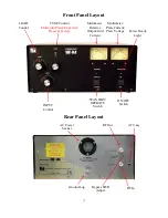
After reading this manual and completing the Installation/Preparation Instructions, position 

the Commander VHF-144 front panel controls as follows: 

   ON/OFF   —  OFF 

   OPERATE/SSTANDBY  —  STANDBY 

   INPUT  —  CENTER ON SCALE (50-55 on Scale) 

   LOAD  —  MINIMUM (COUNTER-CLOCKWISE) (100 on scale is minimum capaci-

tance) 


TUNE  —  LEAVE AT FACTORY SETTING  (NOTE: the TUNE control is a multi-turn 

piston capacitor and was factory preset for operation at 144.200 MHz.   

Factory Setting Tune is 55. 

After presetting these controls, switch the ON/OFF switch to the ON position. The meter 

lamps will illuminate, the blower will be running and plate voltage will be approximately 2800 
VDC. 

The 3CPX800A7 used in this amplifier requires a warm up period before RF drive may be 

applied, to prevent damage to the tube. A 2 minute warm up is provided by a microprocessor 
circuit. During warm-up the green LED will flash at 1sec rate. At the end of the warm-up pe-
riod, the green POWER LED on the front panel illuminates on fully and the unit is ready for 
operation. 

Switch the OPERATE/STANDBY switch to the OPERATE position and key the exciter with 

ZERO

 RF drive applied. The Red Transmit light should illuminate, the tube will be biased 

“on”, and plate idling current should be approximately 60 ma. as displayed on the Ip meter 
scale. 

Apply a very low RF drive (less that 5 watts) and adjust the INPUT control for a peak in the 

plate current (Ip) on the meter. Next adjust the TUNE control for maximum output as indicated 
on an external Wattmeter. DO NOT adjust the LOAD control at this time.  

COMPLETE 

THESE ADJUSTMENTS AS QUICKLY AS POSSIBLE TO AVOID STRESSING THE 
TUBE. 

 Key the exciter in FM Mode (For Tune Procedure), and while increasing the RF drive, adjust 

the LOAD control clockwise in order to keep the grid current below 40ma. and to obtain a peak 
in output power on an external wattmeter (see chart: Typical Operating Conditions chart on the 
next page). 

Re-peak the TUNE control for maximum output at 600ma of plate current. 

The Commander VHF-144 is ready for SSB or CW on the air operation. Normal SSB opera-

tion is indicated by plate current readings on voice peaks of approximately 1/3 to 1/2 of the CW 
key down value. 

For FM or other high duty cycle modes, limit drive to 10-15 watts maximum. 

Содержание COMMANDER VHF-144

Страница 1: ...2 METER LINEAR AMPLIFIER Owner s Manual PALSTAR INC Command Technologies Division 9676 N Looney Road Piqua Ohio 45356 U S A Customer Service and Sales Telephone 800 773 7931 Fax 937 773 8003 E mail i...

Страница 2: ...Procedure 9 Operating Hints 10 Typical Operating Conditions Table 10 Warranty Service and Returns 11 HV Power Supply Schematic 12 AC Mains Step Start Schematic 13 Control Metering Board Schematic 14 R...

Страница 3: ...band An automatic delay circuit for proper cathode conditioning before RF drive is applied which extends tube life This is preformed by a microprocessor which also controls a step start dual relay sy...

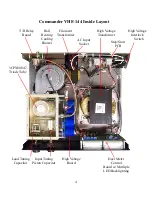
Страница 4: ...lower Load Tuning Capacitor Input Tuning Piston Capacitor 3CPX800A7 Triode Tube Filament Transformer High Voltage Interlock Switch Duel Meter Control Board w Mutliple LED Backlighting High Voltage Boa...

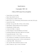
Страница 5: ...adjustable Output Impedance 50 Ohms nominal Antenna Load VSWR 2 1 maximum Harmonic Suppression better than 60db down at rated output Intermodulation Distortion better than 35 dB down at rated output W...

Страница 6: ...internal RF tube compartment covers removed CONTACT WITH VOLTAGES IN THE CABINET CAN BE FATAL CLOSE QUAR TER EXPOSURE TO UNSHIELDED RF AT THESE POWER LEVELS AND FRE QUENCY IS HAZARDOUS TO YOUR HEALTH...

Страница 7: ...ol Multi turn Piston Capacitor Preset at Factory Multimeter Relative Output Grid Current LOAD Control INPUT Control STANDBY OPERATE Switch ON OFF Switch Power Ready Light RF In RF Out Bypass SWR Adjus...

Страница 8: ...e of the unit and between other equipment To switch from transmit to receive the Commander VHF 144 requires a contact closure or keying circuit capable of sinking 15ma of positive voltage 12 VDC open...

Страница 9: ...tion Switch the OPERATE STANDBY switch to the OPERATE position and key the exciter with ZERO RF drive applied The Red Transmit light should illuminate the tube will be biased on and plate idling curre...

Страница 10: ...someone changes these ad justments it will not be necessary to retune the amplifier each time you operate it Just turn the unit on wait for the green light and begin transmitting If you decide later t...

Страница 11: ...ability other than herein stated Shipping Your Amplifier Back to the Factory Due to the necessity of shipping the amplifier with the HV transformer removed please contact the factory for instructions...

Страница 12: ...12 Commander VHF 144 HV Power Supply...

Страница 13: ...13 AC Mains and Step Start Board VHF 144 13 5VAC...

Страница 14: ...14 Control and Metering Board VHF 144...

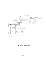
Страница 15: ...15 RF Deck VHF 144...

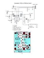
Страница 16: ...16 Commander VHF 144 T R Relay Board...

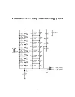
Страница 17: ...17 Commander VHF 144 Voltage Doubler Power Supply Board...

Страница 18: ...18 RF Deck 3CPX800A7 Triode Tube Load Tuning Capacitor Input Tuning Piston Capacitor RF Plate Choke Plate Capacitor 120pf 7 7kv...

Страница 19: ...19 Dual Meters Grid Current Scale 0 60ma Single Tube Top 0 120ma Two Tubes Mid 0 180ma Three Tubes Bottom Grid Current Scale 0 600ma Single Tube Top 0 1200ma Two Tubes Mid 0 1800ma Three Tubes Bottom...

Страница 20: ...20 Meter Board Cathode Fuse...

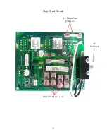
Страница 21: ...21 Step Start Board AC Main Fuse 20A x 2 AC Interlock Step Start Relays x 4...

Страница 22: ...22 Power Supply 470uF Capacitor 450 vdc x 8 HV Sense RF Output...

Страница 23: ...23...

Страница 24: ...24 Palstar Incorporated 9676 N Looney Rd Piqua OH 45356 USA Customer Service and Sales Telephone 1 800 773 7931 Fax 1 937 773 8003 Email info palstar com Version 1 0 2010 03 29...

Отзывы: