


RESTORING THE INDUCTOR WHEEL
Page 8
Notes:
1. A SWR of 1:1 is best, but an SWR as high as 2:1 may be acceptable. Check your
transmitter/amplifier manual for details.
2. If you cannot get an acceptable SWR, lengthen or shorten your antenna and/or
feedlines and retune.\
3. If you get low SWR readings at more than one setting, use the setting that
gives:
- highest FORWARD power reading
- lowest REFLECTED power reading
- uses the largest capacitance (highest number) on the
INPUT and ANTENNA controls
- Adjust the largest capacitance (highest number) on the output control to
keep the losses low, and the voltage that would appear on the antenna capacitor
to within 5 kV.
4. Any time a new or different antenna is connected, it is necessary to repeat the
turning procedure for each antenna.
5. Once every 4-6 months clean the roller coil with Deoxit D5 contact cleaner and
a clean cotton cloth. Do not remove the conducting grease on the rod that guides
the roller wheel. Do not transfer any of the conducting grease from the rod to
the roller coil body, as this will contaminate the windings.
PALSTAR
W h e n a p p r o a c h i n g t h e e n d s t o p s o f t h e r o l l e r i n d u c t o r
( r e a d i n g s o f Z e r o o r 2 2 9 )
S LO W D O W N
. S l a m m i n g t h e
r o l l e r w h e e l i n t o t h e m e c h a n i c a l e n d s t o p s o n e i t h e r
e n d o f t h e r o l l e r i n d u c t o r
w i l l d e c r e a s e t h e p r e s s u r e o f
t h e w h e e l
a g a i n s t t h e w i r e w o u n d o n t h e c e r a m i c f o r m .
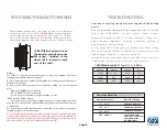
To RESTORE wheel pressure on
the inductor push down on the
flat springs soldered to the
wheel shaft located on each
end of the shaft.
TROUBLESHOOTING
Yo u r h e a r a s p i t t i n g s o u n d w h i l e t u n i n g y o u r AT 4 K a t h i g h
p o w e r.
Yo u a r e p r o b a b l y t u n i n g i n t o a n i m p e d a n c e t h a t i s o n t h e
l o w s i d e ( 2 0
Ω
- 4 0
Ω ) . I n t h i s e v e n t , e i t h e r r e d u c e
t r a n s m i t t e r / a m p l i fi e r p o w e r t o a l o w e r s e t t i n g o r c h a n g e t o a
h i g h e r a n t e n n a i m p e d a n c e b y u s i n g a d i ff e r e n t a n t e n n a o r
m o d i f y i n g t h e e x i s t i n g a n t e n n a .
A s s e e n i n t h e c h a r t t o t h e r i g h t , a n a n t e n n a c a p a c i t a n c e s e t t i n g
t h a t i s t o o l o w u n d e r t h e s e c o n d i t i o n s w i l l r e s u l t i n e x c e s s i v e l y
h i g h v o l t a g e s , h i g h l o s s e s , a n d p o o r e ffi c i e n c y.
I n t h e fi r s t i n s t a n c e t h e t u n e r w i l l a r c a n d s u ff e r a l m o s t 1 6 % l o s s ,
o f w h i c h 8 0 % w i l l b e d i s s i p a t e d i n t h e r o l l e r i n d u c t o r.
Ant Cap
Inductor
Voltage
Loss
100pF
200pF
300pF
11.7
μ H
6
μ H
4
μ H
4550
2400
1600
16%
8%
6%
Antenna Impedance
Max Power Rating
500 watts (all bands)
1000 watts (all bands)
1500 watts (all bands)
160m - 2000 watts
80m - 15m - 2500 watts
10m - 1000 watts
(29.5 MHz max.)
8
Ω -
15
Ω
15
Ω -
25
Ω
25
Ω -
50
Ω
50
Ω -
2000
Ω
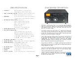
Power Specifications
(assuming single tone key down)
1500 Watts into a 25
Ω l o a d @ 3 . 5 M h z