


Service the PA-7000 Series Firewall Hardware
and the NPC fails after three recovery attempts, the chassis will reboot to attempt to recover the
card.
You do not have to power off the firewall to install or remove NPCs unless the device is in FIPS-
CC mode. If the device is in FIPS-CC mode, you must power off the firewall before adding or
replacing an NPC, otherwise the device will boot into maintenance mode. The procedure to
replace an NPC is the same for both the PA-7050 and PA-7080 firewalls except for NPC slot
numbering.
The following topics describe how to replace an NPC in a single chassis and in a high availability
(HA) configuration and provides details on checking the card slot status as well as how to
troubleshoot an NPC.
•
Replace PA-7000 Series Firewall NPC in a Single Chassis
•
Replace PA-7000 Series Firewall NPC in a High Availability (HA) Configuration
•
PA-7000 Series Front Slot and Card States
•
PA-7000 Series Firewall Network Processing Card (NPC) Troubleshooting Commands
Replace PA-7000 Series Firewall NPC in a Single Chassis
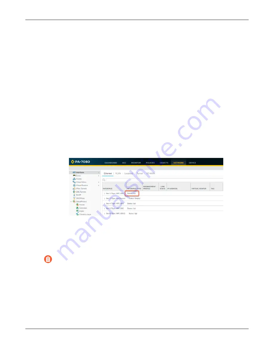
STEP 1 |
Check the status of the NPC that is having a problem. You can do this from the web
interface or from the CLI. In the web interface, navigate to
Network
>
Interfaces
to view
status of each NPC slot.
If the NPC failed due to a hardware problem, the status shows
Failure
. The NPC may also
have a configuration problem, in which case you can run the commit force command to try and
force a commit.
STEP 2 |
Make note of the cable connections and then loosen the screws on each side of the NPC.
Releasing the eject levers on the NPC will trigger a micro switch that powers down the
card to prepare it for removal. Only release the levers if you intend to remove the card.
STEP 3 |
Put the provided ESD wrist strap on your wrist ensuring that the metal contact is touching
your skin. Then attach (snap) one end of the ground cable to the wrist strap and remove the
alligator clip from the banana clip on the other end of the ESD grounding cable. Plug the
banana clip end into one of the ESD ports located on the front of the chassis before handling
ESD sensitive hardware. For details on the ESD port location, see
PA-7000 Series Firewall Hardware Reference
164
©
2023 Palo Alto Networks, Inc.
Содержание PA-7000 Series
Страница 1: ...PA 7000 Series Firewall Hardware Reference docs paloaltonetworks com ...
Страница 6: ...Table of Contents PA 7000 Series Firewall Hardware Reference 6 2023 Palo Alto Networks Inc ...
Страница 22: ...PA 7000 Series Firewall Overview PA 7000 Series Firewall Hardware Reference 22 2023 Palo Alto Networks Inc ...
Страница 24: ...PA 7000 Series Firewall Overview PA 7000 Series Firewall Hardware Reference 24 2023 Palo Alto Networks Inc ...
Страница 32: ...PA 7000 Series Firewall Overview PA 7000 Series Firewall Hardware Reference 32 2023 Palo Alto Networks Inc ...
Страница 98: ...PA 7000 Series Firewall Installation PA 7000 Series Firewall Hardware Reference 98 2023 Palo Alto Networks Inc ...
Страница 123: ...PA 7000 Series Firewall Installation PA 7000 Series Firewall Hardware Reference 123 2023 Palo Alto Networks Inc ...
Страница 128: ...PA 7000 Series Firewall Installation PA 7000 Series Firewall Hardware Reference 128 2023 Palo Alto Networks Inc ...
Страница 208: ...Service the PA 7000 Series Firewall Hardware PA 7000 Series Firewall Hardware Reference 208 2023 Palo Alto Networks Inc ...


