5
OPERATION
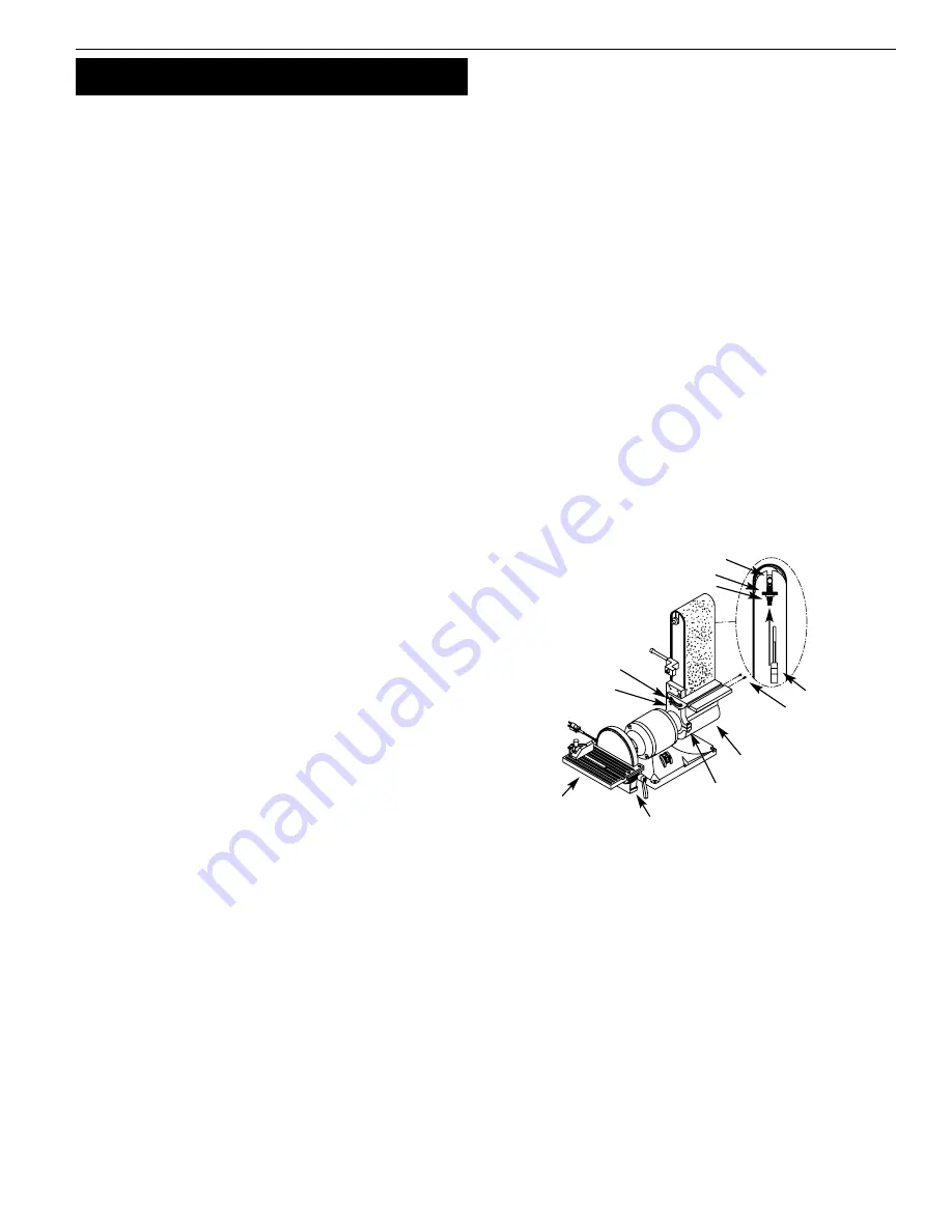
Refer to Figure 7 and 8.
WARNING:
Operation of any power tool can result in foreign
objects being thrown into eyes which can result in severe eye
damage. Always wear safety goggles complying with United States
ANSI Z87.1 (shown on package) before commencing power tool
operation.
CAUTION:
Always observe the following safety precautions:
•
Whenever adjusting or replacing any parts on the tool, turn
switch OFF and remove the plug from power source.
•
Recheck table handles. They must be tightened securely.
•
Make sure all guards are properly attached and securely
fastened.
•
Make sure all moving parts are free and clear of any
interference.
•
Make sure all fasteners are tight and have not vibrated loose.
•
With power disconnected, test operation by hand to verify
clearance and adjust if necessary.
•
Always wear eye protection or face shield.
•
Make sure abrasive belt tracks properly. Correct tracking gives
optimum performance.
•
After turning switch ON, always allow belt to come up to full
speed before sanding or grinding.
•
Be sure motor runs clockwise on disc side. Abrasive belt must
travel down.
•
Keep your hands clear of abrasive belt, disc and all moving
parts.
•
For optimum performance, do not stall motor or reduce speed.
Do not force the work into the abrasive.
•
Support workpiece with belt table when sanding with belt,
with disc table when sanding with disc.
•
Never push a sharp corner of workpiece rapidly against belt or
disc. Abrasive backing may tear.
•
Replace abrasives when they become loaded (glazed) or frayed.
•
When grinding metal, move workpiece across abrasive to
prevent heat build-up.
•
Never attempt wet sanding. If workpiece becomes too hot to
handle, cool it in water.
REPLACING ABRASIVE BELT
Refer to Figure 7.
•
Sanding belt should be replaced when worn, torn, or glazed.
Remove belt dust chute by removing two washer head screws.
•
Release belt tension by pushing tension lever towards idler
drum. Slide old belt off the idler and drive wheels.
NOTE: There may be an arrow on the inside of the belt. The arrow
should point down toward the belt table to ensure that the splice
in the belt will not come apart.
•
Slide new belt over the drive and idler drums; center belt on
drums.
•
Push tension lever towards drive drum to tension belt.
•
Rotate belt by hand to check tracking. Belt should ride centered
on drive and idler drums. Adjust thumb nut as needed to cen-
ter belt on drums. When belt tracks properly, tighten hex nut. If
adjustment of thumb nut does not provide desirable tracking,
adjust the stud using a flat screwdriver. To adjust stud, loosen
hex nut and turn stud counterclockwise to move belt to the
right or clockwise to move belt to the left until belt rides cen-
tered on drive and idler drums. Tighten hex nut while holding
the stud in place.
•
Mount belt dust chute using washer head screws.
ADJUST BELT ASSEMBLY POSITION
Refer to Figure 7.
Sanding belt assembly can be adjusted from horizontal to vertical
position.
•
Loosen socket head bolt that is threaded into pivot bracket.
•
Tilt belt assembly to desired position (from horizontal to verti-
cal). Secure belt assembly position by tightening socket head
bolt in pivot bracket.
ADJUST BELT TABLE
Refer to Figure 7.
•
To adjust belt table angle, loosen socket head bolt.
•
Tilt belt table to desired position. Adjust for
1
/
16
” maximum
clearance between the belt and the table. Secure by tightening
socket head bolt.
HORIZONTAL BELT SANDING
Refer to Figure 7.
•
The belt platen can be tilted from a vertical to a horizontal
position.
•
Remove the belt table by removing the socket head bolt and
flat washer. Loosen the socket head bolt in the pivot bracket;
tilt the belt platen assembly to the horizontal position and
tighten the socket head bolt to secure position.
•
Idler drum can be used as a contact drum to sand curved sur-
faces.
WORK STOP
Refer to Figure 8.
The work stop (Ref. No. 39) can be used instead of the belt table.
•
Remove socket head bolt and flat washer (Ref. Nos. 35 and 36)
holding belt table on pivot bracket. Remove belt table.
•
Mount work stop to pivot bracket using the socket head bolt
and washer (Ref. Nos. 35 and 36).
ABRASIVE BELT FINISHING
Refer to Figure 7.
•
Finishing flat surfaces: Hold workpiece firmly with both hands;
keep fingers away from abrasive belt.
Use work stop. Work stop is used to position and secure work
being sanded. Keep end butted against work stop and move
work evenly across abrasive belt. Use extra caution when finish-
ing very thin pieces.
Figure 7 – Adjusting Assembly
Hex Nut
Belt Dust Chute
Socket Head Bolt
Pivot Bracket
Thumb Nut
Tension Lever
Disc Table
Dust Chute
Release
Stud
Screws
Remove or
Adjust Belt
Table
Palmgren Operating Manual & Parts List
81091A


