


EXTENSION CORD LENGTH (120 VOLTS)
Wire Size
A.W.G.
Up to 25 ft. . . . . . . . . . . . . . . . . . . . . . . . . . . . . . . . . . . . . . . . . . . . . . . . . . . . . .14
25-50 ft. . . . . . . . . . . . . . . . . . . . . . . . . . . . . . . . . . . . . . . . . . . . . . . . . . . . . . . .12
NOTE: Using extension cords over 50 ft. long is not recommended.
EXTENSION CORD LENGTH (240 VOLTS)
Wire Size
A.W.G.
Up to 50 ft. . . . . . . . . . . . . . . . . . . . . . . . . . . . . . . . . . . . . . . . . . . . . . . . . . . . . .18
50-100 ft. . . . . . . . . . . . . . . . . . . . . . . . . . . . . . . . . . . . . . . . . . . . . . . . . . . . . . .16
100-200 ft. . . . . . . . . . . . . . . . . . . . . . . . . . . . . . . . . . . . . . . . . . . . . . . . . . . . . .14
200-300 ft. . . . . . . . . . . . . . . . . . . . . . . . . . . . . . . . . . . . . . . . . . . . . . . . . . . . . .12
NOTE: Using extension cords over 300 ft. long is not recommended.
POWER SOURCE
Drill press requires a 120/240 volt, 60 Hz power source.
To use the drill press with a 240V power supply, have a qualified
electrician attach a 240 volt, 20/30A three-prong plug onto drill
press line cord.
ELECTRICAL CONNECTIONS
Refer to Figure 4.
WARNING:
All electrical connections must be performed by a
qualified electrician. Make sure unit is off and disconnected from
power source while motor is mounted, connected, reconnected or
anytime wiring is inspected.
•
The motor should be wired for 120 volts and clockwise rotation
as viewed from shaft end of motor.
•
A label on the motor describes the possible wiring configura-
tions. There are many different possible combinations, so only
the diagram provided with the motor should be used.
•
The power supply to motor is controlled by a push button
switch. Power lines are connected to the quick connect termi-
nals of the switch.
•
The green ground line must remain securely fastened to the
motor ground terminal to provide proper grounding.
•
To operate drill press at 240 volts, rewire motor as shown in
Figure 4 and replace line cord plug with a 240 volt, 15A, 3-prong
plug. If motor label has a different wiring configuration, use the
motor label diagram to rewire motor.
OPERATION
Refer to Figures 5-9.
WARNING:
Read and understand operating instructions and
parts manual before operating this machine.
CAUTION:
The operation of any power tool can result in foreign
objects being thrown into the eyes, which can result in severe eye
damage. Always wear safety glasses complying with United States
ANSI Z87.1 (shown on package) before commencing power tool
operation.
STARTING AND STOPPING THE DRILL PRESS
Refer to Figure 9.
WARNING:
Be sure drill bit is not in contact with workpiece when
motor is started. Start motor and allow bit to come up to full speed
before drilling.
•
The ON/OFF siwtch (Ref. Nos. 13 and 14) is located on the front
of the head casting.
•
To turn the drill press on, push green ON button. Always allow
drill bit to come up to speed before drilling.
•
To turn the drill press off, press the large red OFF paddle or lift
the paddle and press directly on the red OFF button. Do not
leave drill press untilt he bit has come to a complete stop.
SPEED ADJUSTMENTS
Refer to Figures 5 and 8.
WARNING:
Be sure drill press is turned off and is disconnected
from power source before adjusting speeds.
•
To change spindle speed, loosen motor lock handle (Ref. No.
17), pivot the motor toward front of drill press. This will loosen
the belt and permit relocating the belt to the desired pulley
groove for the required spindle speed (See Figure 5, page 6).
•
After belt has been repositioned, pull handle (Ref. No. 18) to
move motor toward rear of drill press and tighten motor lock
handle.
•
Check belt for proper tension and make any final adjustment. A
belt is properly tensioned when light pressure applied to mid-
point of the belt produces about 1/2” deflection.
TABLE ADJUSTMENTS
Refer to Figure 7.
•
Height adjustments: To adjust table, loosen locking handle (Ref.
No. 14) and turn crank handle (Ref. No. 21) to desired height.
Immediately retighten table bracket locking handle.
•
Rotation of work table : Loosen table locking handle (Ref. No.
14) and rotate table (Ref. No. 11) to desired position and
retighten handle.
•
Tilting work table: Loosen table bolt (Ref. No. 9). Remove pin and
nut (Ref. No. 10). To do this, tighten nut until pin slips out easily.
Tilt table to desired angle up to 45° and retighten table bolt.
Reinsert pin and nut when returning the table to 0° position.
•
To obtain more distance between chuck and table, the work
table can be rotated 180° and base can be used as a work sur-
face. This permits drilling of larger objects.
•
Clamp table securely after adjustments have been made.
DEPTH STOP ADJUSTMENT
Refer to Figure 8.
To control drilling depth, use scale (Ref. No. 39) to adjust to desired
depth. Depress and hold pin, slide depth stop nut (Ref. No. 41)
along lead screw until bottom edge of nut coincides with the
desired depth on the scale, then release pin. Use this feature to drill
more than one hole to the same depth.
MOUNT DRILL BIT
Refer to Figure 8.
WARNING:
Be sure drill press is turned off and is disconnected
from power source before adjusting speeds.
•
Place drill bit in jaws of drill chuck.
•
Tighten chuck with drill chuck key. Be sure to tighten the chuck
using all three key positions on the chuck body and remove
chuck key.
•
Use only the self-ejecting chuck key (Ref. No. 32) supplied with
this drill press, or a duplicate key. Use of any other key might
allow start up with the key still in the chuck. An airborne key
could strike the operator and cause injury.
REMOVE THE CHUCK
Refer to Figure 8.
•
Rotate quill feed handle (Ref. No. 25) until slot is exposed in the
side of the quill (Ref. No. 29). Lock quill in position.
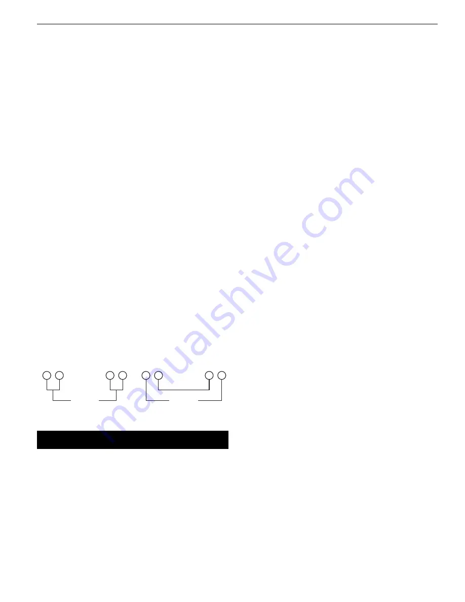
Figure 4 – Wiring Schematic for Motor
120 Volts
1
3
1
3
2
4
2
4
240 Volts
5
Palmgren Operating Manual & Parts List
80207