4
INSTALLATION (CONTINUED)
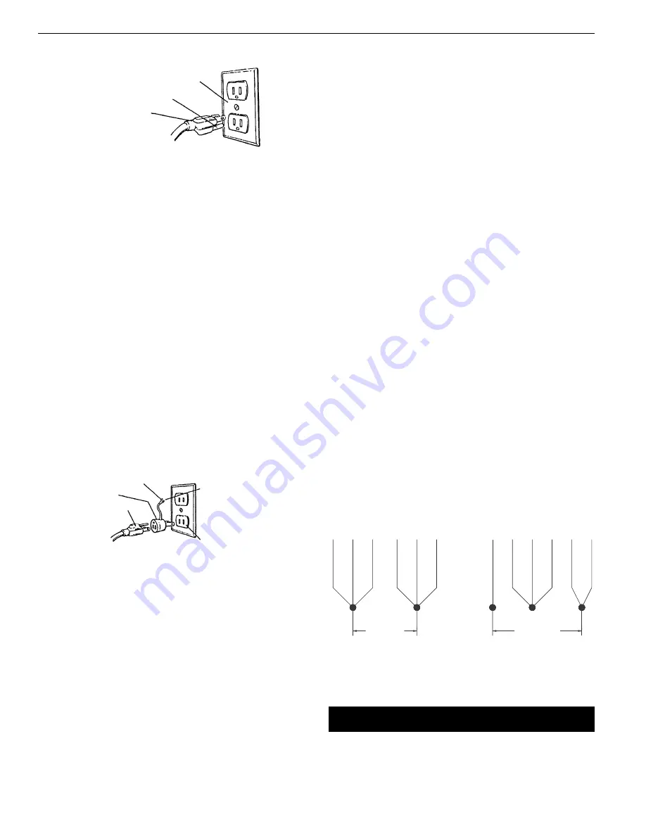
Grounding plug should be plugged directly into a properly
installed and grounded 3-prong grounding-type receptacle, as
shown (Figure 1).
Do not remove or alter grounding prong in any manner. In the
event of a malfunction or breakdown, grounding provides a path
of least resistance for electrical shock.
WARNING:
Do not permit fingers to touch the terminals of plug
when installing or removing from outlet.
Plug must be plugged into matching outlet that is properly
installed and grounded in accordance with all local codes and
ordinances. Do not modify plug provided. If it will not fit in outlet,
have proper outlet installed by a qualified electrician.
Inspect tool cords periodically, and if damaged, have repaired by
an authorized service facility.
Green (or green and yellow) conductor in cord is the grounding
wire. If repair or replacement of the electric cord or plug is neces-
sary, do not connect the green (or green and yellow) wire to a live
terminal.
Where a 2-prong wall receptacle is encountered, it must be
replaced with a properly grounded 3-prong receptacle installed in
accordance with National Electric Code and local codes and ordi-
nances.
WARNING:
This work should be performed by a qualified electrician.
A temporary 3-prong to 2-prong grounding adapter (See Figure 2)
is available for connecting plugs to a two pole outlet if it is
properly grounded.
Do not use a 3-prong to 2-prong grounding adapter unless permit-
ted by local and national codes and ordinances.
(A 3-prong to 2-prong grounding adapter is not permitted in
Canada.) Where permitted, the rigid green tab or terminal on the
side of the adapter must be securely connected to a permanent
electrical ground such as a properly grounded water pipe, a prop-
erly grounded outlet box or a properly grounded wire system.
Many cover plate screws, water pipes and outlet boxes are not
properly grounded. To ensure proper ground, grounding means
must be tested by a qualified electrician.
EXTENSION CORDS
•
The use of any extension cord will cause some drop in voltage
and loss of power.
•
Wires of the extension cord must be of sufficient size to carry
the current and maintain adequate voltage.
•
Use the table to determine the minimum wire size (A.W.G.)
extension cord.
•
Use only 3-wire extension cords having 3-prong grounding
type plugs and 3-pole receptacles which accept the tool plug.
•
If the extension cord is worn, cut, or damaged in any way,
replace it immediately.
EXTENSION CORD LENGTH
Wire Size . . . . . . . . . . . . . . . . . . . . . . . . . . . . . . . . . . . . . . . . . . . . . . . . . . .A.W.G.
Up to 25 ft. . . . . . . . . . . . . . . . . . . . . . . . . . . . . . . . . . . . . . . . . . . . . . . . . . . . . .14
25-50 ft. . . . . . . . . . . . . . . . . . . . . . . . . . . . . . . . . . . . . . . . . . . . . . . . . . . . . . . .12
NOTE:
Using extension cords over 50 ft. long is not recommended.
POWER SOURCE
Drill press requires a 115/230 volt, 60 Hz power source.
To use the drill press with a 230V power supply, have a qualified
electrician attach a 230 volt, 20/30A three-prong plug onto drill
press line cord.
ELECTRICAL CONNECTIONS
Refer to Figure 3.
WARNING:
All electrical connections must be performed by a
qualified electrician. Make sure unit is off and disconnected from
power source while motor is mounted, connected, reconnected or
anytime wiring is inspected.
•
The motor should be wired for 115 volts an clockwise rotation
as viewed from shaft end of motor.
•
A label on the motor describes the possible wiring configura-
tions. There are many different possible combinations, so only
the diagram provided with the motor should be used.
•
Be sure to install motor cord so that the cover plate for the motor
wiring holds the cord in the groove of the motor end shield. The
motor cord must be secured to protect the wiring connections
from possible strain.
•
The power supply to motor is controlled by a locking rocker
switch. Power lines are connected to the quick connect termi-
nals of the switch.
•
The green ground line must remain securely fastened to the
motor ground terminal to provide proper grounding.
•
To operate drill press at 230 volts, rewire motor as shown in
Figure 3 and replace line cord plug with a 230 volt, 15A, 3-prong
plug. If motor label has a different wiring configuration, use the
motor label diagram to rewire motor.
O
OP
PE
ER
RA
AT
TIIO
ON
N
Refer to Figures 4, 5 and 6.
WARNING:
Read and understand operating instructions and
parts manual before operating this machine.
Palmgren Operating Manual & Parts List
80206
Figure 2 – 2-Prong Receptacle with adapter
Grounding Lug
Adapter
3-Prong Plug
2-Prong Receptacle
Make sure this is
Connected to a known
Grounded Receptacle
Figure 1 – 3-Prong Receptacle
Properly Grounded Outlet
Grounding Prong
3-Prong Plug
Figure 3 – Wiring Schematic for Motor
To Change Rotation, Exchange Leads 5 and 6
U, V-Power Supply
115 Volts
1
3
5
2
4
6
230 Volts
1
U
V
U
V
2
3
5
4
6


