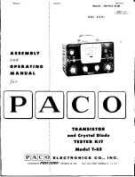
paco T-65 Скачать руководство пользователя страница 10

Содержание T-65

Страница 1: ...__ Manual Net Price 1 00 TRANSISTOR and Crystal Diode TESTER KIT Model T 65 ELECTRONICS CO INC A DIVISION OF PRECISION APPARATUS CO INC 70 31 84th STREET GLENDALE 27 l I N Y J...

Страница 2: ...THE ASSEMBLY OF nus KIT MODEL T 65 INSTRUCTION CORRECTIONS 359 PAGE 19 5TEP 85 CHANGE 1IRED BLACK 125V PR I MARy 1 TO RED GREEN 25V PRI14ARy t1 CHANGE RED BLACK LEAD TO CAl TO RED GREEN LEAD TO CAlli...

Страница 3: ...amage to meter 2 lebo Collector cut off current from 2 microamperes on the first meter range to 50 milliamperes full scale reading in 5 separate ranges 0 100 Microamperes Full Scale 0 500 Microamperes...

Страница 4: ...y any packing materials until all parts are accounted for Each part should be checked against the parts list at the back of the manual to make certain all parts are present and correct as to value and...

Страница 5: ...ollowing are some of the more important points to be remembered 1 Only good quality solder with a non corrosive rosin core should be used THIS IS IMPORTANT ALL GUARANTEES ARE VOIDED AND WE WILL NOT RE...

Страница 6: ...ONG NOSE PLI ERS MAKING GOOD MECHANICAL CONNECTION PRIOR TO SOLDERING LEADS SECURELY CRIMPED TO TERMI NAL SOLDERING A CONNECTION IICOLDII SOlDERED CONNECTION GOOD SOlDERED CON IECTI ON WRONG WRONG WRO...

Страница 7: ...e connection 5 To properly make a solder connection a Apply iron to joint and hold until joint heats sufficiently to melt solder b Apply solder to joint and iron simultaneously allowing solder to flow...

Страница 8: ...d should perform satisfactorily However on occasion improper in strument operation may be traced to a faulty tube or component Should replacement of a part be necessary write directly to PACO Electron...

Страница 9: ...out with a colored pencil each wire and component on the wiring diagram after installation The Solder and Don t Solder designations in the instructions are self explanatory and should be complied with...

Страница 10: ...re use spaghetti from SF 4 Solder to SF 6 Don t Solder I 4 Connect a length of solid bare hook up wire use spaghetti from SF 7 Don t Solder to SF 32 Don t Solder Be sure to connect this wire to both l...

Страница 11: ...id bare hook up wire from SF 40 Solder toSF 29 Don t Solder 15 Connect a length of solid bare hook up wire use spaghetti from SF 39 Solder to SF 43 Don t SOlder vr 16 Connect Rl 5600 10 carbon reSisto...

Страница 12: ...to extreme counterclockwise poSition 25 Connect a length of solid bare hook up wire from SC 2 Don t Solder to SC 4 Don t Solder 26 Connect R8 333 30 1 carbon precision reSistor from SC 8 Solder to SC...

Страница 13: ...h rivet holes in bttse of lugs bend leads back on opposite side of board to hold resistor in place while soldering then solder and trim off excess leads y 33 Connect R6 220 10 carbon resistor red red...

Страница 14: ...0 OJ eLl CD t N S T 1 W r cw C e 0 c O O V I T I I T I to I SE 6 I 150V E D c J 1 0 i t r t 1 2 3 t5 i CB A l m 6 t oF db M 4...

Страница 15: ...EWS FIGURE 8 y 38 Install SD ON OFF slide switch in cutout at location SD Position terminals as shown in Figure 5 Use two 4 40 x 1 4 BH screws two 4 hex nuts and two 4 lockwashers NOTE Do NOT bend swi...

Страница 16: ...PANEL LOCKWASHER 3 8 tiiiiil 318 PANEL WASHER HEX NUT i I 3 8 HEX NUT CHASSIS 3 8 PANEL 318 PANEL LOCKWASHER LOCKWASHERjl 3 8 3 8 PANEL iiiIiiHiiJE l SHER w 3 8 HEX NUT HEX NUT FIGURE 9 C3refully remo...

Страница 17: ...gth of red solid hook up wire from SF 20 Solder to lug J on the meter terminal board Solder j Y i 1 51 Connect a 14 1 2 length of green solid hook up wire from SF 23 Solder to lug G on the meter termi...

Страница 18: ...D I 0 YELLOW GREENevi 6 ORANGE WwltiullRllb RED s KEEP THE HORIZONTAL RUN OF WIRES BLACK ____ TOGETHER AND CLOSE TO THE FROSTED PLASTIC METER BARREL T1 G c III Y 0 0 0 f T 1 I 0 V f T 1 f T 1 CO r 0 E...

Страница 19: ...ire from clip N on meter terminal board Solder to SD 1 Solder Y 70 Connect a 2 length of black thin wall stranded hook up wire from D 1 Solder to E 1 Don t Solder After soldering D 1 examine solder jo...

Страница 20: ...0 Q 1 0 CD 00 T 1 G c c I T 1 LEGEND YELLOW K t RED SPAGETTI ti 0W w W 2 4 GREEN1 7 9 Q HOLES OFFSET FROM CENTER LI NE f 4...

Страница 21: ...e extra care to make a good solder joint at SC 4 vyr 82 Connect R17 320n 1 wire wound precision reSistor from SB 11 Solder to SC 2 SOlder Use extra care to make good solder jOints at SB 11 and SC 2 FI...

Страница 22: ...GREEN YELLOW BLACK BROWN GRAY BLUE RED RED YEL RED WH REO BRN RED BLUE YEl GRAY 6 rn ED CC 1fiIiIIE lPJIII l a1l p e YEl BlK YEl GRN YEL BRN YEL BLUE BRN BlK GRN WH REO GRN BLK GRN RED BlK 8 lItR_ TI...

Страница 23: ...he black 36V transformer lead to SA 14 Solder Connect the white green 43V transformer lead to SA 15 Solder Connect the green black 58V transformer lead to SA 16 Solder Connect the yellow 72V transform...

Страница 24: ...for good contact grip t 117 Install the small pOinter knob on ADJUST LINE control shaft Rotate control to approximate center of its range Position white index mark on knob to T in ADJUST Tighten knob...

Страница 25: ...tion Selector to NPN SHORT Clip lead 4 to 2 and depress READ METER I button Meter pointer should read 100 on 0 100 scale within 3 divisions NOTE Should meter read above 100 reset ADJUST LINE control u...

Страница 26: ...g as in Step 12 14 Set Function Selector to PNP GX5 and repeat reading as in Step 12 15 Set Function Selector to NPN L and repeat reading as in Step 12 except reverse YOM test leads 16 Set Function Se...

Страница 27: ...both normal and depressed positions 26 Repeat Step 25 for PNP GXl NPN GX1 and NPN GX5 27 Remove YOM test prods Set All switch to 1 B switch to 1t5 and Function Selector to ItDf Take a crystal diode kn...

Страница 28: ...th two 6 32 x 3 8 oval head screws two 6 32 hex nuts and two 6 lockwashers for each hinge See Figure 14 To assemble first mount one of the hinges then place one end of handle on mounted hinge Next ins...

Страница 29: ...rts t st 27 Ln 640n YEllS TRANSISTOR FIGURE 15 IIlcbo Test Circuit Figure 16 The emitter circuit is left open for this test Proper voltage is selected by the setting of the A switch Collector polarity...

Страница 30: ...IER V C I 1SY O SOOA 22JL IVAC 560 n 320 n Ra 250JL GREEN E C BlK FI GURE 18 YEl 100 MFO CRYSTAL DIODE Cathode BlK 320 11 RB FIGURE 19 Of Diode Forward Test Circuit Figure 19 The circuit for testing f...

Страница 31: ...r the com plete list of collector voltages available through Switch A Switch A also selects AC voltages in the Df Diode Forward Current test 3 Switch B is the base current injection selector for gain...

Страница 32: ...eir appropiate symbols When an N and a P type of material are joined and a voltage of the proper polarity is applied electrons will flow from N to P and holes will move from P to N Considering the PNP...

Страница 33: ...ation between AC and DC Beta readings under these conditions Other symbols may be encountered by the technician They will however folloW the same pattern as those just described A diffused junction PN...

Страница 34: ...ENSITNITY TO TEMPERATURE CHANGES TRANSISTORS SHQULD NOT BEHELD IN THE HAND DURING TESTS SINCE THIS CONTACT IS ENOUGH TOCHANGE THE TRANSISTOR OPERATION Check the zero setting of the meter needle before...

Страница 35: ...f Switch C had been set to Position 1 the meter will now be reading between 0 100 microamperes However if the switch had been set to Position 2 the meter is between 0 500 microamperes In this case all...

Страница 36: ...to terminal 4 black of Model T 65 Connect of diode to terminal 2 yellow of Model T 65 NOTE It is extremely important that the diode be connected properly as described above otherwise the diode and ins...

Страница 37: ...obtain a separate replacement cover from PACO Electronics Co To remove the cover insert a small screwdriver or knife blade under one of the upper corners and gently pry upwards Being a friction fit th...

Страница 38: ...SB P14 286 1 5 Position Rotary Switch Switch B SC P14 285 I i 5 Position Rotary Switch Switch C CONTROLS SWITCHES Cont Ref Part No No Quantity Description SD PI4 171 1 1 t 13PST Slide SWitch ON OFF S...

Страница 39: ...his plan automatically provides up to date sets of data during a one year subscription period for the nominal fee of only 2 00 per year or four sets of data during a two year subscription period for o...

Страница 40: ......

Страница 41: ......

Страница 42: ......

Страница 43: ...and produced under the auspices of a major test equipment manufacturer The Finest Electronic Test Instruments IN KIT FORM Ip IA lc lo ELECTRON CS CO INC A DIVISION OF PRECISION APPARATUS CO INC 70 31...

Страница 44: ...FlGUf 640J l I0 0 SF RED MARK 560 n J 27 l n_ 10 0 FIGU I I I I I 2 1 2 3 5 6 k _...

Страница 45: ...640 n 1 r I lo I1 Jh 6400 tl I FIGURE 12 1 0 J8Bl o SF 27 1 n 1 560 n RED MARK FI GURE 1 J 5 6 7 8 9 10 11 12...

Страница 46: ...ORANGE GREEN YELLOW a i BLACK BROWN GRAY BLUE RED 11 p RED YEL l E 6 RED WH i l 3 RED BRN IF RED BLUE YEL GRAY YEL BLK YEL GRN YEL BRN YEL BLUE BRN BLK GRN WH RED GRN BLK GRN...

Страница 47: ...1NIOd SIH 1 1 1 NO d 11 318 1 3Z33nOS d...

Страница 48: ...___ SOLDER THIS 1LUG TO CONTROL FLANGE RED DOT CA SE f i I i I I Q c o I Q I 0 _ _w_ ________ _ ______ ____________ __ g 0 M Q 00 0 Q Z o FI M s 0 I 00 00 Sill...

Страница 49: ...00 9 0 I I I I I I I E o 1 2 3 oF M FIGURE 5...

Страница 50: ...r LEGEND YELLOW 61 GREEN N r WU ORANGE UIIl Jllllllln b RED KEEP THE HORIZONTAL RUN OF WIRES BLACK ____ TOGETHER AND CLOSE TO THE FROSTED PLASTIC METER BARREL o o G F...

Страница 51: ...YELLOW WIRE TO TERMINAL 13 OF SECOND DECK o E o GREEN WIRE TO TERMINAL 23 OF SECOND DECK FIGURE 10...

Отзывы: