


Chapter 6
175
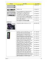
LCD
ASSY LCD MODULE 15.6"W WXGA GLARE W/
ANTENNA*2, CCD 1.3M, BLACK - GTW
6M.WSS02.001
LCD COVER IMR-BLACK GW
60.WSG02.001
LCD BEZEL FOR W/CMOS GW
60.WSG02.003
ANTENNA WLAN-MAIN
50.R4F02.005
ANTENNA WLAN-AUX
50.R4F02.006
LCD CABLE FOR W/CMOS
50.R4F02.007
LCD BRACKET R&L
33.R4F02.003
CAMERA 1.3M
57.R4F02.001
INVERTER
19.R4F02.001
CCFL LCD CMO 15.6"W WXGA GLARE N156B3-
L0B LF 200NIT 10MS 500:1 (LOW COST)
LK.1560D.013
CCFL LCD LPL 15.6"W WXGA GLARE
LP156WH1-TLC1 LF 220NIT 16MS 400:1
LK.15608.013
Category
Description
Acer Part No.
Содержание ENTK36 Series
Страница 6: ...VI ...
Страница 10: ...X Table of Contents ...
Страница 66: ...56 Chapter 3 4 Detach the WLAN module from the WLAN socket ...
Страница 76: ...66 Chapter 3 5 Lift the speaker module clear of the device ...
Страница 78: ...68 Chapter 3 5 Lift the power board from the upper cover and pull the FFC cable through the opening ...
Страница 87: ...Chapter 3 77 10 Disconnect the Bluetooth cable from mainboard ...
Страница 92: ...82 Chapter 3 8 Remove the LCD assembly from the lower cover ...
Страница 103: ...Chapter 3 93 5 Lift the microphone set clear of the panel ...
Страница 109: ...Chapter 3 99 4 Replace the adhesive tape securing the microphone cable and the antenna together ...
Страница 114: ...104 Chapter 3 4 Replace the adhesive tape securing the inverter board cable to the LCD cover ...
Страница 115: ...Chapter 3 105 Replacing the Camera Module 1 Place the camera module in the LCD cover 2 Connect the camera cable ...
Страница 120: ...110 Chapter 3 7 Replace the adhesive tape to secure the antennas to the lower cover ...
Страница 123: ...Chapter 3 113 5 Connect the fan cable ...
Страница 130: ...120 Chapter 3 4 Connect the USB cable to the mainboard and lock the connector ...
Страница 134: ...124 Chapter 3 Replacing the Upper Cover 1 Place the upper cover on the lower cover as shown ...
Страница 135: ...Chapter 3 125 2 Connect the following three 3 cables to the mainboard 3 Connect and lock the power board FFC A A B C ...
Страница 136: ...126 Chapter 3 4 Connect the speaker cable B 5 Connect and lock the touchpad FFC C ...
Страница 138: ...128 Chapter 3 Replacing the RTC Battery 1 Place the RTC battery into the mainboard connector ...
Страница 140: ...130 Chapter 3 4 Slide the HDD module in the direction of the arrow to connect the interface ...
Страница 198: ...Appendix A 188 ...
Страница 206: ...196 Appendix C ...
Страница 210: ...200 ...