


Chapter 5
TROUBLE SHOOTING GUIDE
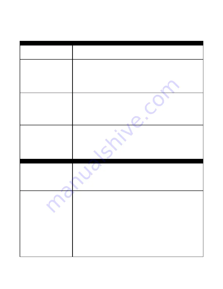
NO AUDIO WHEN
KEY(S) IS PRESSED
NO DIAL TONE WHEN
THE # KEY IS PRESSED
THE VISITOR CAN'T
HEAR THE TENANT
FROM THE SYSTEM
BUT THE TENANT CAN
HEAR THE VISITOR
THE TENANT CAN'T
HEAR THE VISITOR
TALKING BUT THE
VISITOR CAN HEAR
THE TENANT
THE LIQUID CRYSTAL
DISPLAY (LCD) SHOWS
QUESTION MARKS
(????)
THE LIQUID CRYSTAL
DISPLAY (LCD) IS
BLANK, NO DISPLAY AT
ALL
The AeGIS 9000 does not provide a tone when key is pressed, but the ribbon cable's
red line must be facing down and connected on pin 1 on the LCD's terminal pin connec-
tor on the board.
• Check the phone line using a standard phone, make sure you get dial tone.
• Check the speaker and microphone connection on the board. The snap on clip
connector on the speaker and microphone connector must be facing inside the board.
• Check the red and orange wires, make sure they are soldered into the speaker.
• Turn the system's power "OFF" and disconnect the speaker connector from the board.
Set your meter to Ohm and use 50 Ohm scale or higher. Put the two probes into the
speaker (+) and (-) (polarity not important) and the meter should read about 19-24
Ohms.
• Check the speaker and microphone connection. The snap on clip connector on the
speaker and microphone connector must be facing inside the board.
• Check the red and orange wires, make sure they are soldered into the speaker.
• Press the # key as soon as you hear a dial tone, tap your finger into the
microphone and you should hear a finger tap sound from the speaker.
• Check the speaker and microphone connection. The snap on clip connector on the
speaker and microphone connector must be facing inside the board.
• Check the brown and black wires, make sure they are soldered into the microphone.
• Turn the system's power "OFF" and disconnect the speaker connector from the board.
Set your meter to Ohm and use 50 Ohm scale or higher. Place the two probes into the
speaker (+) and (-) (polarity not important) and the meter should should read between
19 - 24 Ohms.
• Turn the unit power "OFF" and "ON".
• Erase the memory chip (EEPROM) using Function Code 50. If you have trouble to log
on to programming mode, press and release the square red button then press #.
• The power LED must be "ON" (LED2 marked on the board).
• The Power Switch's toggle must be on the left position ("ON").
• Check the fuse (3 Amp 250 Volt).
• Measure the voltage on AC1 and AC2 (set your voltmeter to AC and place the probes
on AC1 and AC2), it should read within 12VAC-13.8VAC or if you use 12 VDC, the
meter must read 13.5 - 14.0 VDC.
• The LCD's ribbon cable has red dots along the side. The red dots must be facing
down. It must be connected to the terminal marked number 1.
• The LCD's ribbon cable sits tight on the terminal pins marked LCD on the board.
• The LCD's ribbon cable is connected into the LCD's terminal pins connector and the
red dots along the side of the ribbon should be connected on pin 1.
• Adjust the LCD's intensity.
• Turn the system's power "OFF", wait for 15 seconds and turn it "ON".
• If the sunlight hits directly into the the LCD, block the sunlight. If the LCD is readable
after you block the sunlight, you may have to move the system to a different location
Pach and Company
Chapter 5
Page 37
AeGIS 9000 Series
TROUBLE SHOOTING GUIDE
AUDIO PROBLEM S
SOLUTIONS AND SUGGESTIONS
DISPLAY PROBLEM S
SOLUTIONS AND SUGGESTIONS


