


32
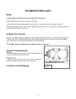
Figure 8
TROUBLESHOOTING (cont’d)
Step Three:
(figure 8)
Locate the drive belt adjustment screw (item 2 in fig 8) in the lower front
end of the treadmill. Insert the allen wrench into the drive belt adjustment
screw and turn the screw 1/2 turn clockwise.
Step Four:
(figure 7)
Complete the adjustment by tightening the four motor mount
screws (item 1 in fig 7).
Step Five:
Walk on the treadmill to determine if the slippage is decreased or
eliminated.
Step Six:
If no improvement is observed, the hesitation may be caused by a loose
tread belt - see "Tread belt tension adjustment" below. If improvement is
noticed but slippage is still present, repeat steps 2 through 5. If you tighten the drive belt adjustment screw 1 1/2 turns and there is still
hesitation (slippage) contact your authorized PaceMaster dealer. Tightening the drive belt adjustment screw more than 1 1/2 turns can
result in bearing damage to the motor and/or drive roller.
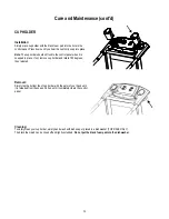
Tread Belt Tension Adjustment
This step requires the 3/16” T handle allen wrench that came with
your treadmill.
Step One:
Locate the two tread belt adjustment screws (#3 & #4 in fig 9) as
shown.
Step Two:
Turn both the left and right tread belt adjustment screws 1/2 turn
clockwise.
Step Three:
Walk on the treadmill to see if the adjustment you made
decreased the slippage.
Step Four:
If a significant decrease in slippage was observed, go to step 2. If you tighten the tread belt 1 1/2 turns per side and slippage is still
present, do not continue to adjust the tread belt tension. Contact your authorized PaceMaster dealer.
Figure 9
Keep Tread belt
Reasonably Centered
3
4


