background image

 11

DISPLAY

DISPLAY

DISPLAY

DISPLAY
MESSAGE

MESSAGE

MESSAGE

MESSAGE

DESCRIPTION

DESCRIPTION

DESCRIPTION

DESCRIPTION

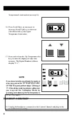
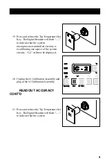
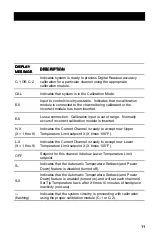
C-1 OR C-2

Indicates system is ready to process Digital Readout accuracy
calibration for a particular channel using the appropriate
calibration module.

CAL

Indicates that system is in the Calibration Mode.

E-5

Input to control circuitry unstable.  Indicates that no calibration
module is connected to the channel being calibrated or the
incorrect module has been inserted.

E-6

Loose connection.  Calibration input is out of range.  Normally
occurs if incorrect calibration module is inserted.

H-X
(X = 1 thru 9)

Indicates the Current Channel is ready to accept new Upper
Temperature Limit setpoint X (X times 100°F).

L-X
(X = 1 thru 9)

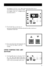
Indicates the Current Channel is ready to accept new Lower
Temperature Limit setpoint X (X times 100°F).

OFF

Setpoint for this channel is below Lower Temperature Limit
setpoint.

S--

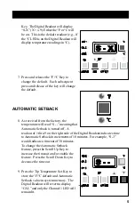
Indicates that the Automatic Temperature Setback (and Power
Down) feature is disabled (turned off).

S-X

Indicates that the Automatic Temperature Setback (and Power
Down) feature is enabled (turned on) and will set each channels'
Set Tip Temperature back after X times 10 minutes of handpiece
inactivity (non-use).

---
(flashing)

Indicates that the system circuitry is proceeding with calibration
using the proper calibration module (C-1 or C-2).

Содержание 6993-0133

Страница 1: ...r local authorized PACE dealer or contact PACE directly at Telephone 301 490 9860 Fax 301 604 9215 PACEIncorporated 9893 Brewers Court Laurel MD 20723 1990 MBT 250 220 CALIBRATION KIT PACE P N 6993 01...

Страница 2: ...ractor StripTweez SwaPlater ThermoBand ThermoPart ThermoPik ThermoJet ThermoTweez Thermo Drive VisiFilter The following are trademarks and or servicemarks of PACE Incorporated Laurel Maryland U S A an...

Страница 3: ...PTION 1 An optional KeyLock feature is available from PACE which prevents unauthorized alteration of stored data or calibration of the system Check the rear panel of the system power source If the Key...

Страница 4: ...the system LEDs will light TheTemperatureDisplaywillread 888 and change to read 1 X 5 Release the Tip Temperature Set and Scroll Down Keys The Temperature Display will now read CAL and only the three...

Страница 5: ...meaning that Automatic Setback is turned off A readout of 1 thru 9 on the right side of the Digital Readout indicates time toAutomatic Setback in increments of 10 minutes For example S 3 would indicat...

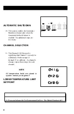
Страница 6: ...matic Setback feature is enabled No additional steps are necessary CHANNEL SELECTION 11 The Channel 1 LED is now lit signifying that Channel 1 is ready for calibration Perform steps 12 through 21 to c...

Страница 7: ...ys as necessary to increase Scroll Up Key or decrease Scroll Down Key the Lower TemperatureLimitvalue 14 Press and release the Tip Temperature Set Key to store the display value into memory UPPER TEMP...

Страница 8: ...he displayed value into memory TheDigitalReadoutwillnow display C 1 NOTE Ifyoudonotwishtorecalibrateforreadout accuracy press theTIPTEMPERATURE OFFSETKeyandperformsteps12through 17 Afterallchannelshav...

Страница 9: ...processor controlled circuitry is recalibrating one aspect of the system circuity C 2 will now be displayed 20 Unplug the 1 Calibration Assembly and plug in the 2 CalibrationAssembly READOUT ACCURACY...

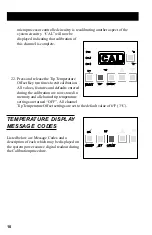
Страница 10: ...to exit calibration All values features and defaults entered during the calibration are now stored in memory and all channel tip temperature settings are turned OFF All channel Tip Temperature Offset...

Страница 11: ...t calibration module is inserted H X X 1 thru 9 Indicates the Current Channel is ready to accept new Upper Temperature Limit setpoint X X times 100 F L X X 1 thru 9 Indicates the Current Channel is re...

Страница 12: ...12...

Отзывы:

Похожие инструкции для 6993-0133