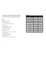


Model Wire Fuse
VA700.1 4AWG 70Amp
VA2000.1 1/0AWG 200Amp
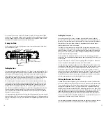
Power Connections:
The power cable needs to be connected directly to the battery with the recommended
gauge wire. Never connect to the fuse box for main amplifier power. Before starting
choose the easiest route from the battery to the amplifier that is free of moving mechani
-
cal parts or sharp metal that may bind or damage the power cable. The following are
guidelines for running power cable through the vehicle.
1. Use grommets when passing power wire through any wall (firewall or floor pan).
2. Avoid running power over engine components or near heater cores.
3. Use an inline fuse installed near (within the first 18”) the battery, to help protect the
power wire and prevent fires from a short circuit (damage to power due to collision,
excessive heat, etc…).
4. Be sure to solder all ring terminals to prevent loose or isolated connections.
5. It is also recommended that the charging wire from the alternator to the battery be
upgraded to the same gauge as the power wire as a minimum(bigger is better).
Ground Connections:
TThis wire should be the same gauge as the power wire. Make sure to use a different
color wire (normally black) to prevent confusion and reversed power connections at the
amplifier. Here are the guidelines for connecting the ground wire properly.
1. Avoid using seat bolts, seatbelt bolts, and non-structural metal pieces of the chassis
for ground.
2. For applications up to 8 gauge wire, the floor pan can be used for ground
connection. Be sure to remove all paint, grease, and oil from the area before drilling and
attaching your ground bolt (not a ground screw).
3. If a power wire of 4 gauge or larger is being used (multiple amplifiers or when
improved current flow is desired) the ground straps must be upgraded. These are the
connections from the battery to the frame and the frame to the chassis.
4. Your ground bolts should have lock washers and star washers to insure good contact.
5. Ring terminals should be soldered and have direct contact with the ground source.
6. After all the ground connections are made, spread silicone over the bolt to prevent
rust and moisture from entering the vehicle.
Remote turn on:
This terminal must be connected to a 12-volt switched source to make the amplifier
operational. As a rule, the remote turn on lead is provided by an aftermarket head
unit. This connection will turn the amplifier on or off whenever the head unit is turned
on or off. This is done to prevent unnecessary current draw on the battery. Generally
this wire will be blue or blue with white stripe, and as always verify this circuit with your
DMM before making your connection. If a factory head unit is being utilized the power
antenna wire should be used provided it registers 12-volts when energized (colors vary
from make, model, and year). If neither one of these options is available a 12-volt source
interrupted by a switch can be used. A 16 – 18 gauge wire is recommended for this con
-
nection and to prevent inducted noise it is suggested that this wire be routed with the
power wire.
Signal Inputs:
IIn order to achieve the utmost clarity and output from your new Oz Audio amplifier sys
-
tem the signal path must be clean. The recommended signal cable would be in the form
of high-end RCA’s, if you are unsure as to which use, consult your local authorized Oz
Audio dealer.
These signal cables will run from the rear of the head unit to the amplifier. As with the
power cable it should be routed away from sharp objects and sharp bends to prevent
damage to the signal cable. It is also recommended that this cable be routed on the
opposite side of the power cable (power wire down the driver’s side and signal cable
down the passenger’s side or vice versa), away from large wire looms and fan motor
wires. All of these precautions are to avoid inducted noise into the amplifier.
Once this cable is run, you can connect them to the amplifier through the jacks marked
input, take a minute to verify that left and right into the amp are matched with left and
right out of the head unit as well as for front and rear channels.
Speaker Connections:
Vector mono amplifier systems are designed to reach their output potential at 1-ohm
mono. Lower impedances will send the amplifier into protection and may possibly dam
-
age the electronics inside. To held avoid this possibility we have included these formu
-
las to help determine the load put onto the amplifier.
Formula for parallel:
Impedance divided by the # of coils = New Impedance.
For instance, let’s say we have two dual 4-ohm subwoofers.
7
6


