RT1003 Manual
Revision:
190628
17
Co-ordinate frame conventions
An inertial navigation system is capable of making very precise measurements, but without
context those measurements are just meaningless numbers. In order to make sense of the
world, and to output measurements in way that describes position, orientation and velocity, an
INS such as the RT1003 uses a number of different reference frames and co-ordinate systems.
This section describes those frames and co-ordinate systems.
IMU frame
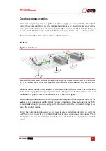
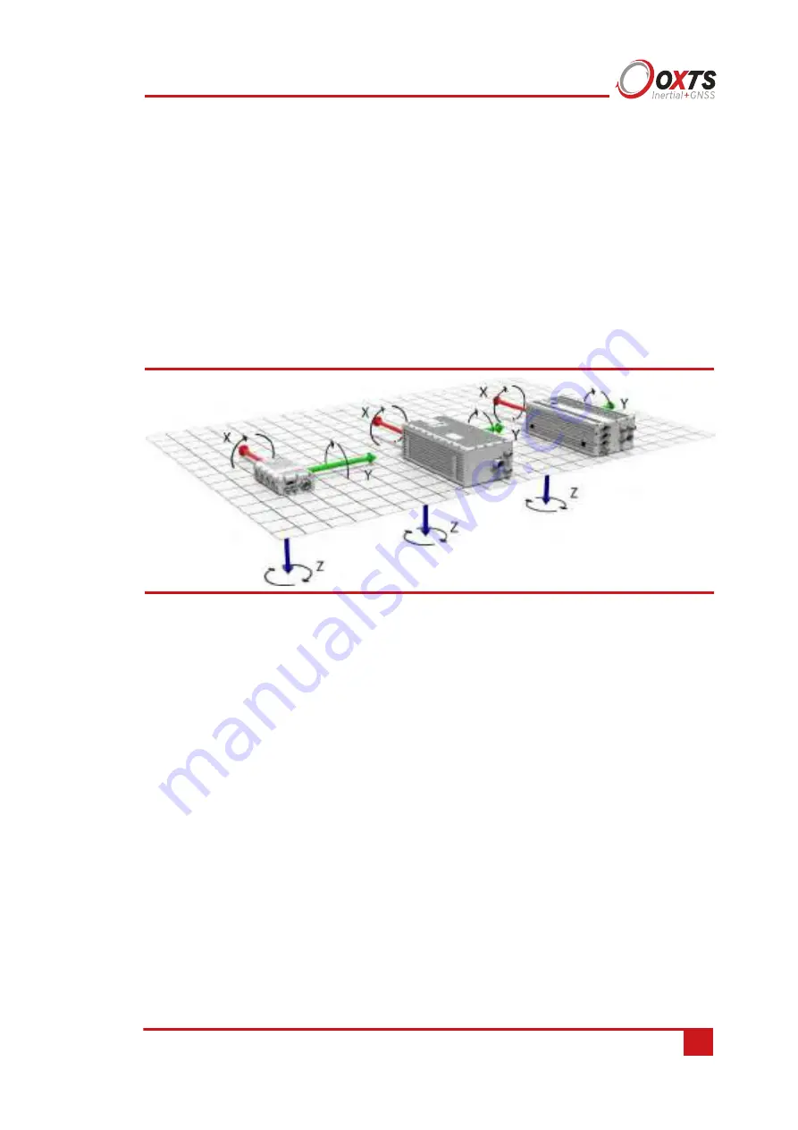
Figure 3.
IMU frame
The arrows indicate the positive direction, and the direction of positive rotation about each axis. The origin of the
IMU frame is marked on the casing of each product or described in the technical drawings at the end of the user
manual.
All of our inertial navigation systems share a common IMU reference frame. The orientation
of that frame is popular among navigation systems. The positive direction of each axis, and
the direction of positive rotation about those axes is shown in Figure 3.
When looking at the connector panel of your product, the positive X-axis points forward, the
positive Y-axis points right and the positive Z-axis points down. The exact origin of the IMU
frame is marked on the product casing and is also described in the technical drawings at the
end of the product manual.
During the configuration process, you will need to enter several measurements in order for
the INS to know where it is mounted in relation to other components or objects. When
making those measurements, always measure between the IMU frame origin and the point of
interest.
Содержание RT1003
Страница 1: ...Confidently Accurately User Manual RT1003 GNSS aided inertial navigation system ...
Страница 108: ...Confidential Information Oxford Technical Solutions ...
Страница 110: ......

