background image


Version1.0 rev 18 Feb 2015 

Rotr 


1.2.  D

ISCLAIMER 


Andor Technology assumes no liability for the use of the information contained in this document or the 
software which it describes. The user assumes all risks. There is no warranty of fitness for a particular 
purpose, either express or implied.  
The information contained in this document is assumed to be correct, but in no event shall Andor 
Technology be held responsible for typographical errors or changes in the software not reflected in this 
document.  
 
The specifications contained in this document are subject to change without notice.  
Any changes or modifications not expressly approved in this manual could void your authority to operate 
this equipment.  
 
If you require further information about this unit, you may contact your local representative. The latest 
contact details for your local representative may be found at our website: 

www.andor.com


1.3.  T

RADEMARKS


Andor and the Andor logo are trademarks of Andor Technology. Andor Technology is an Oxford 
Instruments company. All other marks are property of their owners. All other trademarks mentioned in this 
document are the property of their respective owners, and are used herein solely for informational purposes 
only.  
 
Changes are periodically made to the product and these will be incorporated into new editions of the 
manual. New releases of the manual are available through MyAndor: 

http://my.andor.com/login.aspx


Содержание ANDOR Rotr

Страница 1: ...Hardware Guide Andor Technology 2015 Rotr Version 1 0 rev 18 Feb 2015 ...

Страница 2: ...eel Functions 11 SECTION 4 INSTALLATION 12 4 1 Installing the Rotr Filter Wheel 12 4 1 1 Location and Mounting 12 4 1 2 Assembly 13 4 1 3 Power Connection and Protective Earthing 13 4 2 Installing Cables 13 4 2 1 Power and Signal Cabling 13 4 3 Installing the Software 13 SECTION 5 USING THE ROTR FILTER WHEEL 14 5 1 Emergency Disconnection 14 5 2 Instructions for Use 14 5 3 Power Up Sequence 14 5 4...

Страница 3: ...us 20 Get Filter Wheel Configuration 23 Set Wheel Position 25 Set Shutter State 26 Reset 26 Examples 27 APPENDIX C OTHER INFORMATION 28 Terms and Conditions of Sale and Warranty Information 28 Waste Electronic and Electrical Equipment Regulations 2006 WEEE 28 REVISION HISTORY Version Released Description C 21 Jan 2013 Initial Release 1 0 18 Feb 2015 Presentation updated to current Formatting enhan...

Страница 4: ...on from ionising radiation Any customer using this product in such an application should provide their own protection 14 This is a Class A product In a domestic environment this product may cause electromagnetic interference in which case the user may be required to take adequate measures 15 This equipment has been tested and found to comply with the limits for a Class A digital device pursuant to...

Страница 5: ...s manual should be read in conjunction with all relevant manuals supplied with your system Please not that some of the equipment described in this manual may not be included in the set you have purchased 1 1 HELP AND TECHNICAL SUPPORT If you have any questions regarding the use of this equipment please contact the representative from whom your system was purchased or Europe Andor Technology 7 Mill...

Страница 6: ...ications not expressly approved in this manual could void your authority to operate this equipment If you require further information about this unit you may contact your local representative The latest contact details for your local representative may be found at our website www andor com 1 3 TRADEMARKS Andor and the Andor logo are trademarks of Andor Technology Andor Technology is an Oxford Inst...

Страница 7: ...is controlled through the software Figure 1 View of the Rotr showing the main hardware features MOTOR The enclosed motor rotates the filters between the required filter positions FILTER WHEEL The filter wheel contains up to 10 filters STAND The stand enables the Rotr to be set to the correct optical height and secured to the optical table Filter Wheel with filters Stand Motor ...

Страница 8: ... connections is outlined below Figure 3 Rotr connections panel PWR POWER For connection to the 24 V DC power supply unit AUX I O For connection to an approved suitable shutter using pins 4 and 7 Figure 4 AUX I O pinouts OUT RS 232 connection for connection to additional filter wheels By using the RS 232 connection you can control up to three high speed filter wheels by daisy chaining the devices a...

Страница 9: ...9 Version1 0 rev 18 Feb 2015 Rotr Figure 5 Outline view showing connections for up to 3 Filter wheels IN RS 232 connection for connection to the control PC In Out In Out In PC Rotr A Rotr B Rotr C ...

Страница 10: ...w encompasses a range of complementary components both hardware and software that fit seamlessly together creating a complete confocal microscopy solution A flexible component focus also allows us to provide key pieces of hardware as stand alone Figure 6 Overview of Rotr integrated into a typical system PC running iQ Precision Control Unit PCU Andor Laser Combiner ALC with MPU Head iXon Spinning D...

Страница 11: ...xceptionally high switching speeds and is mounted at an angle between the CSU and camera for optimum performance with no back reflections The Rotr filter wheel has the following functions Houses powers and controls up to 10 filters of 25mm diameter Is controlled by PC based software via a RS 232 cable supplied Controls the filter position and speed of switching Allows the control of up to 3 filter...

Страница 12: ...onditions Operational vibrations should be eliminated Ensure the stand is fully clamped to the optical table using 2 screws per clamp ring where possible Power cabling and control cables should be routed to prevent accidents damage and accidental unplugging Installation into a Revolution System by an Andor Installation Technician or trained Andor Systems distributor will include the following step...

Страница 13: ...power before connecting disconnecting cables from the product A mains power cable is provided with this product but ensure that it satisfies local regulations for safety Mains power is connected via the 3 pin IEC C14 connector on the rear panel of the product An integral part of protection against electric shock in the case of a fault is the protective earth provided via the earth conductors in th...

Страница 14: ...ion Technician or trained Andor Systems distributor 5 3 POWER UP SEQUENCE 1 Power up the Rotr filter wheel The motor should be audible as the filter wheel is turned to confirm the 0 position filter 2 Wait 1 minute to allow the Rotr device to stabilise 3 Power up the workstation 4 Wait for 5 minutes to allow the system to fully boot up and stabilise 5 Enable the control software Please refer to sof...

Страница 15: ...lvents cleaning agents or aerosols 6 2 REGULAR CHECKS The state of the product should be checked regularly especially the integrity of the enclosure and the mains cable Do not use equipment that is damaged 6 3 ANNUAL ELECTRICAL CHECKS It is advisable to check the integrity of the insulation and protective earth of the product on an annual basis e g U K PAT testing Do not use equipment that is dama...

Страница 16: ...er tool Be careful not to over tighten once the ring is clamping the filter into the installed position 5 Ensure the filter is fully retained and has no free play by lightly shaking the filter wheel 6 Re install the access panel using a flat head screwdriver or similar tool and screwing clockwise ...

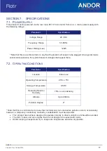
Страница 17: ...ear there 7 2 OPERATING CONDITIONS Parameter Specification Location Indoor use Operating Temperature 23 C 5 C Storage Temperature 0 50o C Operating Relative Humidity 70 non condensing Altitude Up to 2000 m Pollution Degree 2 Note that this is a technical term to say that normally only non conductive pollution occurs occasionally however a temporary conductivity caused by condensation must be expec...

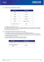
Страница 18: ... of moisture e g dripping spraying submersion etc 7 4 TRANSPORT STORAGE SPECIFICATIONS The packaging used for the original delivery should be retained for further use This product must be shipped in accordance with the international standard ETS 300119 Class 2 1 System functional performance shall be maintained following exposure to a Storage Transportation temperature range of 0 C to 50 C The pac...

Страница 19: ...19 Version1 0 rev 18 Feb 2015 Rotr APPENDIX A MECHANICAL DRAWINGS Dimensions in mm inches ...

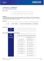
Страница 20: ...meout Bytes 0 10 0 1 2 3 4 5 6 7 8 9 10 0xCC WAST WBST WCST SAST SBST SAMOD SMOD 0x0D Byte 0 0xCC Bit 7 6 5 4 3 2 1 0 Name 1 1 0 0 1 1 0 0 Byte 1 WAST Wheel A Speed and Position Bit 7 6 5 4 3 2 1 0 Name 0 SPD2 SPD1 SPD0 POS3 POS2 POS1 POS0 Description Wheel speed 000 0 Speed 0 001 1 Speed 1 010 2 Speed 2 011 3 Speed 3 100 4 Speed 4 101 5 Speed 5 110 6 Speed 6 111 7 Speed 7 Wheel position 0 9 0000 ...

Страница 21: ...Position 3 0100 4 Position 4 0101 5 Position 5 0110 6 Position 6 0111 7 Position 7 1000 8 Position 8 1001 9 Position 9 Byte 4 WCST Wheel C Speed and Position Bit 7 6 5 4 3 2 1 0 Name 1 SPD2 SPD1 SPD0 POS3 POS2 POS1 POS0 Description Wheel speed 000 0 Speed 0 001 1 Speed 1 010 2 Speed 2 011 3 Speed 3 100 4 Speed 4 101 5 Speed 5 110 6 Speed 6 111 7 Speed 7 Wheel position 0 9 0000 0 Position 0 0001 1 ...

Страница 22: ...7 6 5 4 3 2 1 0 Name 1 1 0 1 1 SHST2 SHST1 SHST0 Description Shutter state 010 1 Open 011 2 Open on ext trigger 100 3 Closed Byte 7 SAMOD Shutter A Mode Bit 7 6 5 4 3 2 1 0 Name 1 1 0 1 1 SMOD2 SHMOD1 SHMOD0 Description Shutter Mode 011 3 Not Connected 100 4 Normal operation Byte 9 SAMOD Shutter B Mode Bit 7 6 5 4 3 2 1 0 Name 1 1 0 1 1 MOD2 SHMOD1 SHMOD0 Description Shutter Mode 011 3 Not Connect...

Страница 23: ... FD hexadecimal immediately and requests configuration information from a daisy chained wheel The configuration information of the whole chain is returned after a 1 4s timeout Bytes 0 4 0 1 2 3 4 0xFD 1 0 3 Bytes 5 9 5 6 7 8 9 W A WHLACFG Wheel A configuration NC Not Connected ER Error 25 25mm 32 32mm Bytes 10 14 10 11 12 13 14 W B WHLACFG Wheel B configuration NC Not Connected ER Error 25 25mm 32...

Страница 24: ... 15 16 17 18 19 W C WHLCCFG Wheel C configuration NC Not Connected ER Error 25 25mm 32 32mm Bytes 20 24 20 21 22 23 24 S A SHATYP Shutter A Type VS Vincent Shutter Bytes 25 29 25 26 27 28 29 S B SHBTYP Shutter B Type VS Vincent Shutter Bytes 30 30 ...

Страница 25: ... Wheel speed 000 0 Speed 0 001 1 Speed 1 010 2 Speed 2 011 3 Speed 3 100 4 Speed 4 101 5 Speed 5 110 6 Speed 6 111 7 Speed 7 Wheel position 0 9 0000 0 Position 0 0001 1 Position 1 0010 2 Position 2 0011 3 Position 3 0100 4 Position 4 0101 5 Position 5 0110 6 Position 6 0111 7 Position 7 1000 8 Position 8 1001 9 Position 9 Response Byte 1 command byte as received returned immediately Byte 2 0x0D af...

Страница 26: ...it 7 6 5 4 3 2 1 0 Name 1 0 WHL1 WHL0 1 SHFUN2 SHFUN1 SHFUN0 Description Wheel selection 10 2 wheel A 11 3 wheel B Shutter state 010 2 open 011 3 open on ext trigger 100 4 close Response Byte 1 command byte as received returned immediately Byte 2 0x0D after task completion RESET Byte 1 0xFB 7 6 5 4 3 2 1 0 1 1 1 1 1 0 1 1 Response 0x0D ...

Страница 27: ...o position 0 at maximum speed 10000000 80 128 Wheel B moves to position 0 at maximum speed 11111100 00000000 FC 00 252 0 Wheel C moves to position 0 at maximum speed 00110110 36 54 Wheel A moves to position 6 at speed 3 10101010 AA 170 Shutter A opens 10101100 AC 172 Shutter A closes 10111010 BA 186 Shutter B opens ...

Страница 28: ... sale including warranty conditions will have been made available during the ordering process The current version may be viewed at http www andor com pdfs literature Andor_Standard_Warranty pdf WASTE ELECTRONIC AND ELECTRICAL EQUIPMENT REGULATIONS 2006 WEEE The company s statement on the disposal of WEEE can be found in the Terms and Conditions ...

Отзывы: