

STEP 12- Mount electric control box assembly to unit and fasten it with
original screws.
Figure 12
STEP 9- Fasten the wires with the strap and screws provided.
STEP 11- Cover and fasten the lid with two screws provided.
STEP 10- Connect the ground wire:Low Ambient Control Box
to Outdoor Unit Control Box.
Figure 11
Figure 9
Figure 8
Outdoor Fan Motor
- Connect the Outdoor Fan Motor black wire with the grey wire
of the ICM325-HN Module with the terminal.
Manufacturer reserves the right to change, at any time, specifications and designs without notice and without obligations.
4
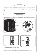
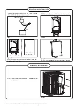
Mounting control assembly
Mounting electrical box
Figure 10
Outdoor Unit
Control Box
Low Ambient Control Box


