

Part Number 10400099-101 04/2007
©2007 Overland Storage, Inc.
W
Page
Part Number 10400099-101 04/2007
©2007 Overland Storage, Inc.
W
Page
4. Install Chassis in a Rack
WARNING: INSTALL MULTIPLE UNITS IN THE RACK FROM THE
BOTTOM UP. EXTENDING A UNIT THAT HAS EMPTY SPACES
BENEATH IT MIGHT CAUSE THE RACK TO TIP FORWARD AND
CAUSE PERSONAL INJURY OR DAMAGE TO EQUIPMENT.
Overland RECOMMENDS THAT TWO PEOPLE ARE USED TO
SUPPORT AND SLIDE THE UNIT INTO THE RACK.
Your REO 9100 array comes with a set of slide rails for
mounting the array chassis in the 19-inch rack. The unit
has a 5U form factor. The inner rail segments are already
attached to the chassis.
Install chassis in rack as follows:
1.
Identify the screw holes in the front and rear vertical
rails of the rack where the slide rails will be installed.
2.
Slide out the middle slide rail segments from the outer
rails and set them aside.
3.
Assemble the outer rail with the bracket to the
required length.
a.
Fit the outer rail in the bracket so that the rail slides
freely inside the bracket.
b.
Position the unsecured rail/bracket assembly in the
rack and adjust the length.
NOTE: The slide rail assembly ears must fit against the
inside surfaces of the vertical rack rails.
c.
Align the proper bracket holes with the slots at the
end of the rail.
d.
Insert the screws from the rail side, then through
the bracket holes, and secure loosely with the nut
plate against the bracket (
Do not tighten
the screws at this time.
Figure 1. Attaching bracket to outer slide rail
4.
Attach the rail/bracket assembly to the vertical rack
rails (
).
a.
Position the rail/bracket assembly inside the rack,
with the bracket to the rear of the rack.
b.
Ensure the mounting ears fit against the inner
surfaces of the vertical rack rails.
c.
Insert screws from the outside through the rack rail,
then through the mounting ear of the rail/bracket
assembly, and secure into the nut plate positioned
on the inside, against the mounting ear.
Figure 2. Attaching slide rail assembly to rack
5.
Verify that the rail assemblies are installed properly
and tighten all the screws.
NOTE: The screws that secure the bracket to the outer rail
should be tightened last (they were left loose in
.d).
6.
Insert the previously removed middle rail segments
into the mounted outer rails from the rear of the rack.
7.
Pull out the middle slides from the front of the rack so
that they lock (click) in the extended position.
CAUTION: The next step should be performed by at least
two people, or by using a mechanical lift. Make certain that
when the chassis is fully extended, a force of 20% of the
rack’s weight, but not more than 130 lb. (59 Kg), applied in
any direction other than upwards, does not cause the rack
to tip over.
8.
Install the Chassis in the slide rails.
a.
At the front of the rack, lift the chassis to its install
height and engage the inner slides mounted on the
chassis with the middle slides protruding from the
rack. Slide the chassis in until you hit a stop.
b.
Simultaneously press both lock buttons on the
chassis-mounted inner rails to allow them to slide
farther into the rail assembly. You will hit a stop
(click) when the locks engage.
c.
Press the same lock buttons again and slide the
chassis all the way into the rack.
9.
Slide the chassis in and out several times, ensuring
that the inner and outer slide locks engage and the
chassis does not bind against the slides.
If binding occurs, loosen the screws that secure the
slides to the front and rear rails and adjust as needed.
10.
Secure the chassis in the rack with screws through the
front panel ears (left and right side) into the nut plates.
5. Install Hard Drives in the Chassis
The disk drive assemblies (disks mounted in carriers) are packaged separately, which allows you to insert them into the
array chassis after you have installed the chassis in the rack. Each disk carrier contains a label that identifies the slot
into which you must insert it (
).
Figure 3. Drive numbering and location in chassis
IMPORTANT: The array is configured to use the RAID 5 and
Logical Volumes setup option. Failure to install the disks in
the corresponding slots may result in the need to create a
new configuration.
IMPORTANT: Do not remove the drives from their trays.
Doing so will void the drive warranty.
Install drive carriers in chassis as follows:
1.
Insert the first disk carrier in to the applicable slot in
the chassis.
2.
Push firmly on both sides of the carrier to ensure that
the latch and connector are fully seated. The lever
should be in open position.
3.
Press the lever in until it clicks into the locked position.
This draws the carrier fully into the slot and seats it
properly inside the chassis.
4.
Repeat these steps for each disk carrier.
NOTE: To maintain proper airflow and cooling, a disk drive or a
blank drive carrier must be installed in every slot of the chassis.
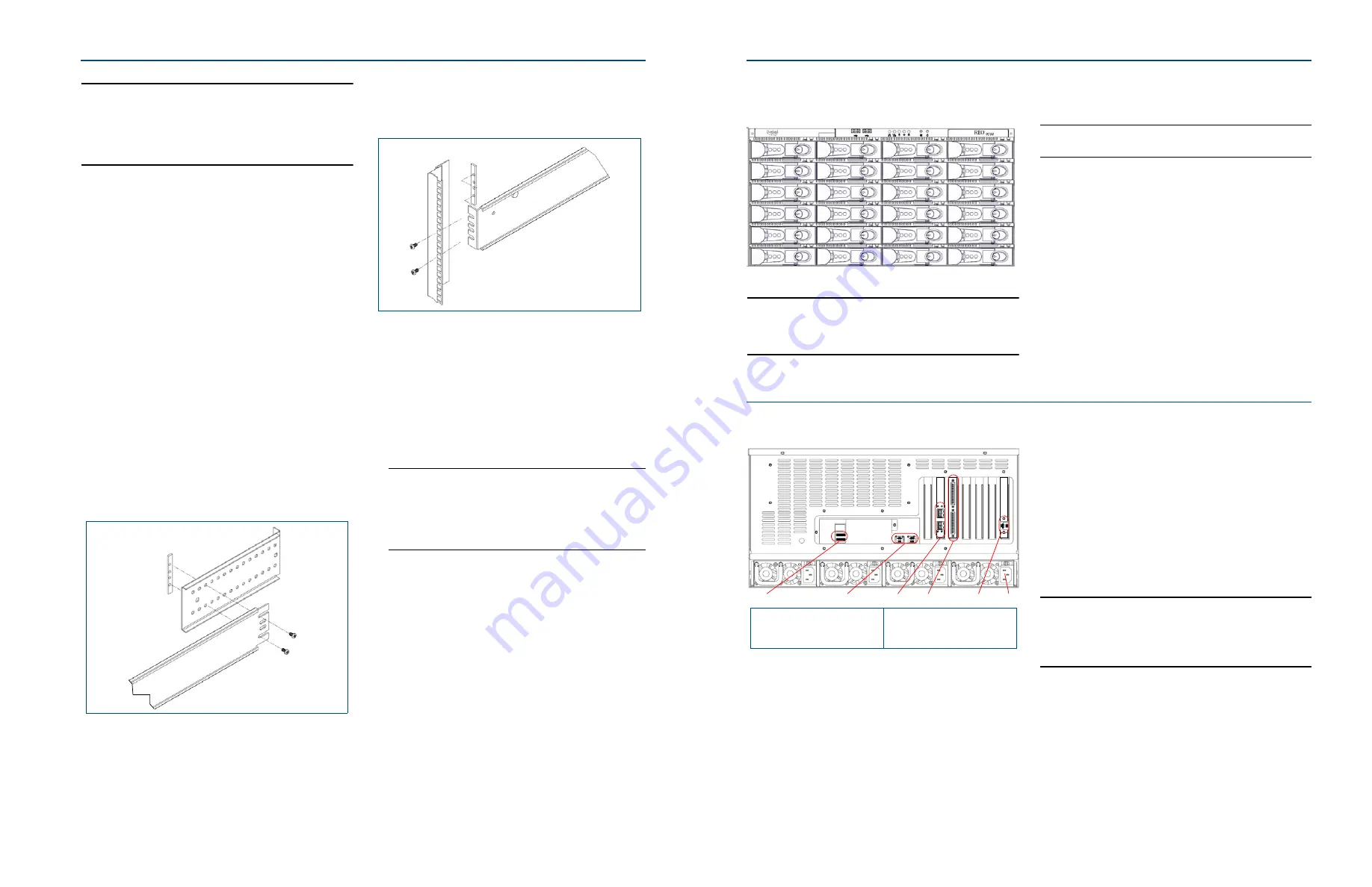
6. Connect USB SoftKey and Management PC
All cabling and power connections are located on the rear
panel of your REO array (
Figure 4. REO 9100 array rear panel connections
NOTE: You can manually edit the files on the USB SoftKey to
enter the applicable gateway address and the different address
for each port, or you can connect your management system to
Data Port 1 and configure all the port information via the REO
GUI. The following steps tell you how to configure via the GUI.
(This procedure is for Windows. If you are using UNIX, the steps
may be slightly different.)
Connect USB SoftKey and cables as follows:
1.
Make a backup copy of all the files on the USB SoftKey
before and after
you configure it.
2.
Using a Category 5e (or better) cable, connect Data Port
1(GbE) on the array to a PC that is temporarily
configured to use a 10.0.0.<n> IP address and a subnet
mask of 255.255.255.0.
3.
Insert the USB SoftKey into one of the USB ports.
Overland strongly recommends that you use the upper
slot on the back.
4.
Attach
all
power cords to the array, and plug them into
the AC mains.
IMPORTANT: You must connect and use all power cords.
If
one of the cords is disconnected or malfunctioning, the
array beeps repeatedly until the situation is resolved.
Overland recommends that you use separate power mains
for the power sources.
5.
If power is automatically enabled when you attach the
cords to an AC power source, shut down the array using
the Power button (
) before continuing with the
setup process.
00
04
08
12
16
20
01
05
09
13
17
21
02
06
10
14
18
22
03
07
11
15
19
23
6
1
2
3
4
5
1 - Dual USB ports
2 -
Data Ports 1 (right) and 2 (left)
3 -
FC Ports 0 (lower) and 1 (upper)
(present on FC units only)
4 -
SCSI Connectors
5 -
Management Port (RJ45)
6 -
AC Power connectors (4 pl.)
2 of 4
3 of 4


