H
B
A
J
C*
Jamb
10“
Steel
Wood
Concrete/
Masonry
10“
10“
10“
10“
E
Drill
Size
4“
3/8“ exp. anchor
Use ANSI B95.12
carbide tipped
drill bit
3/8“*
3/8“ bolt
3/8“ Lag
4“
4“
4“
4“
D*
Doors
10“
All
All
7/16“
5/16“
Table 1 - Headplate Fasteners
All
10“
10“
10“
10“
F**
Fastener
Specifications
4“
6“
4“
8“
6“
Operation
Operator
Fastener
Push Up
790
790
780
780
Reduced
Chain Drive
Door Type
G
8“
10“
8“
12“
10“
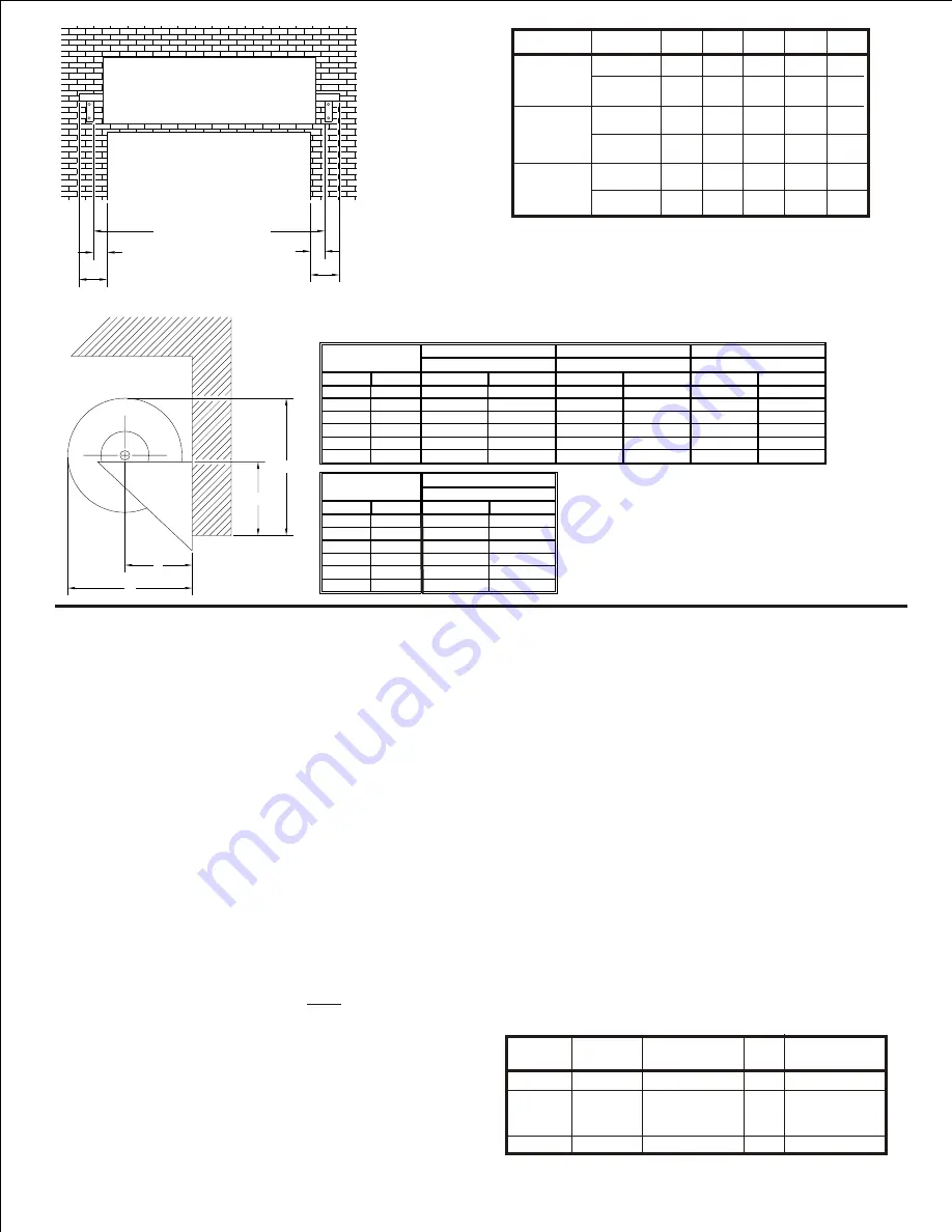
Figure 1
*Excess shaft may be cut off of non-drive sides of
doors for additional clearance. It is recommended that
at least 1” of shaft be retained past the headplate to
facilitate spring tension adjustment.
**Dimension “F” applies to Drive End only.
RH shown, LH opposite.
*Drill size for supplied fasteners. For others, refer to
manufacturer’s specified installation method.
790
780
10“
10“
6“
6“
12“
light weight building jambs from twisting.
Bracing may be required to prevent
NOTES
INSTALLATION
5” above top of guide, if headroom allows)
E, H and G (Figure 1).
1. Locate headplates per dimensions F, (or approximately
2. Hold headplates in mounting position. Using a water
3.
IF DOOR IS CHAIN DRIVEN:
top hole in headplates.
Fasten headplates to wall using three fasteners. Use
the wall. If this condition exists then use Thru-bolt.
unit (CMU) wall.
DO NOT
install fastener in a void in
for brick or stone walls or hollow concrete masonry
Mark mounting hole locations on header. See Table 1
for supplied fasteners.Thru-bolts are recommended
level, check to make sure tops of headplates are level.
OPENING WIDTH + G
E
C
D
F
FOR REFERENCE
DRIVE END
3
a. Remove hardware from package.
b. Slide 1/2“-13 nut and 3/8” external tooth locking
washer over bolt as shown in Figure 2. (Note:
Sharp edges of locking washer must be in contact
with flange of self clinching nut).
c. Thread self clinching nut onto threads of bolt and
snug until finger tight.
d. Insert assembly into one of the 3 outer mounting
holes on end ring.
e. Use a backup wrench(channel lock, vise grips or
equivalent) to prevent 1/2“ nut from spinning while
torquing bolt to seat self clinching nut.
f. While maintaining pressure to keep assembly
seated against ring, use a 9/16“ ratchet, wrench
or power driver to turn the bolt and secure the self
clinching nut.
g. Tighten bolt until self clinching nut is fully seated.
(Resistance against the back up wrench will be felt
as clinching nut begins to seat).
h. With backup wrench still applied to 1/2“ nut,
reverse torque on bolt to remove.
I. Repeat for 2 remaining holes.
j. Place bearing into recess of bracket. (Figure 2)
k. Bolt sprocket to bracket to capture bearing.
l. Slide bracket assembly over shaft, and align
appropriate legs to self clinching nuts in ring.
m. Bolt to ring as shown.
n. Thread hand chain thru chain guide slots, over
chain wheel and connect ends. NOTE: Make sure
chain is not twisted.
o. Slide chain hoist assembly onto door shaft.
p. Install drive chain to sprocket and hoist assembly.
Align both sprockets and tighten set screw on
hoist.
q. Install chain keeper to wall.
See Page 4 For Ilustration
Over
Up To
-
7' 8"
7' 9"
9' 4"
9' 5"
11' 0"
11' 1"
12' 8"
12' 9"
14' 3"
14' 4"
16' 0"
Opening Height
Recommended
Minimum
20 1/4"
18 1/4"
21"
19"
21 3/4"
20 3/4"
22 3/4"
21 3/4"
23 1/4"
22 1/4"
24 3/4"
23 3/4"
B
Head Room
Over
Up To
Recommended
Minimum
Recommended
Minimum
Recommended
Minimum
-
7' 8"
10"
8"
9 1/8"
Same
18 1/8"
Same
7' 9"
9' 4"
10 1/2"
8 1/2"
9 1/8"
Same
18 3/8"
Same
9' 5"
11' 0"
11"
10"
10 1/4"
Same
19 3/4"
Same
11' 1"
12' 8"
11 1/2"
10 1/2"
10 1/4"
Same
20 1/4"
Same
12' 9"
14' 3"
12"
11"
10 1/2"
Same
20 1/2"
Same
14' 4"
16' 0"
13"
12"
10 1/2"
Same
21"
Same
Opening Height
H
J
A
Head Plate Height
Axle Setting
Back Room


