


8
3
4
N.C. on tether
1
N.C. on tether
Green
Green/White
Spare twisted
pair
5
6
N.C. on tether
N.C. on tether
Brown
Brown/White
Spare twisted
pair
7
8
Fathom-X -
Fathom-X +
Blue
Blue/White
Fathom-X pair
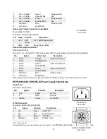
Output Low Voltage Connection to BlueRov2
Power Cable: 03-0161
Connector: 3.5mm Bullet, female
Pin Signal Function
Description
1
+15V
ROV
Power
15V, 1000W supply, Red
2
GND
GND
Ground Input, Black
Data Pass through to BlueRov2
Data Cable: 03-0162
Connector: 4 x 3 Position
0.1”
Crimp Connector with Housing, female (center pin not populated)
Pin
Signal
Wire Color
Description
1
2
Spare
Spare
Orange
Orange/White
Spare twisted pair
3
4
Spare
Spare
Green
Green/White
Spare twisted pair
2
5
6
Spare
Spare
Brown
Brown/White
Spare twisted pair
2
7
8
Fathom-X -
Fathom-X +
Blue
Blue/White
Fathom-X pair
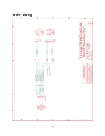
Note: All 4 pairs are wired up to the 8pin tether connector using a 1-1 connection by wire color.
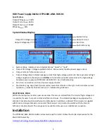
OTPS1KW-ASM-TOPSIDE-R2 Power Supply Connections
Input Power
Connector: IEC 320-C13
Pin
Signal
Function
Description
1
Line
Power
AC Line
2
E
GND
Ground
3
Neutral
Power
AC Neutral
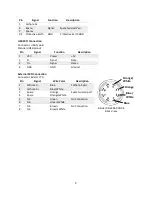
Tether Connection
Connector: Binder 09-6504-000-08
Pin
Signal
Function
Description
1
HV+
Power
+200 VDC
2
N.C.
N.C.
No Connection
3
HV-
Power
-200 VDC
4
Fathom-X-
Signal
Fathom-X pair
1
N.C. = No Connect
2
Green and Brown spare twisted pairs are connected in the OTPS1KW-ASM-ROV-R1 for possible future expansion.
MC-BH-8-M
Face View
Binder 09-6504-000-08
Face View
IEC 320-C13
Face View
Содержание OTPS1KW-ASM-ROV-R1
Страница 10: ...10 Tether Wiring...


