

Page 7
Page 8
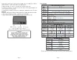
Specifications
1-Module Chassis Common Specifications
Model
Number
All Models
Module
Capacity
1
Regulatory
Compliances
UL, CE, FCC Class A, NEBS Level 3, RoHS, WEEE, REACH
Dimensions
W x D x H
3.8” x 5.5” x 1.0” (96.52 mm x 139.7 mm x 25.4 mm) - 3.3/5.0 watt models
3.8” x 6.0” x 1.0” (96.52 mm x 152.4 mm x 25.4 mm) - 8.3 watt models
Weight
1.5 lbs. (0.68 kg)
Temperature
Commercial: 0 to 50°C
Wide:
-40 to 60°C
Extended: -40 to 75°C (8.3 watt models only)
Storage: -
40 to 80°C
Humidity
5 to 95% (non-condensing)
Altitude
-100m to 4,000m
Warranty
Lifetime warranty with 24/7/365 free Technical Support
AC Power Specifications
Description
1-Module AC
1-Module AC
1-Module AC
Model Number
8240-1
8241-1
8240-2
8241-2
8242-x, 8243-x
Input Power
Requirements
(typical)
100 to 240VAC,
50 / 60Hz
0.13A @ 120VAC
100 to 240VAC,
50 / 60Hz
0.19A @ 120VAC
100 to 240VAC,
50 / 60Hz
1.0A @ 120VAC
Output Power
3.3 watts
1A @
3.3VDC
5.0 watts
1.5A @
3.3VDC
3.3 watts
1A @
3.3VDC
5.0 watts
1.5A @
3.3VDC
8.3 watts
2.5A @
3.3VDC
Power
Connector
2.5mm Barrel Connector)
2.5mm Barrel Connector)
2.1mm Barrel Connector
MTBF (hrs)
250,000
100,000
260,000
DC Power Specifications
Description
1-Module 48VDC
Model
Number
8242-9, 8243-9
Input Power
Requirements
20 to 60VDC*
0.6A Max
Output Power
8.3 watts
2.5A @ 3.3VDC
Power
Connector
3-Pin Terminal (Isolated)
MTBF (hrs)
2,700,000
* Effective range is 18 to 60VDC when using a module without dying gasp support.
Prepare a power cable using a three conductor insulated wire (not supplied) with 12AWG to
14AWG thickness. Cut the power cable to the length required.
Strip approximately 3/8 of an inch of insulation from the power cable wires.
Connect the ground wire to the ground terminal on the chassis by fastening the stripped end
to the DC power connector (ground).
Connect the power cables to the chassis by fastening the stripped ends to the DC power
connector.
WARNING:
Note the wire colors used in making the positive, negative and ground connections.
Use the same color assignment for the connection at the circuit breaker.
Connect the power wires to the circuit breaker and switch the circuit breaker ON.
Rear of 1-Module Power Chassis,
Models 8242-9 and 8243-9 with DC Power Connector
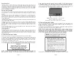
NEVER ATTEMPT TO OPEN THE CHASSIS OR
SERVICE THE POWER SUPPLY. OPENING THE
CHASSIS MAY CAUSE SERIOUS INJURY OR DEATH.
THERE ARE NO USER REPLACEABLE OR
SERVICEABLE PARTS IN THIS UNIT.
WARNING!!!


