8 of 25
9 of 25
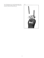
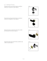
Insert the Alignment Bars into the Single Knuckle Dum-mies and lock each in place using M2 x 5 mm Countersunk Torx Screw and the T6 Screwdriver (fig. 13).
Fig. 13:
Страница 1: ...i digits Component Assembly Guide...
Страница 2: ...l prior to fabrication It is highly recommended that the use of this manual is made in conjunction with instruction from a clinician experienced in the use of i digits Refer to www touchbionics com do...
Страница 3: ...e Dummies 8 3 0 Inputs and Finishing Options 10 3 1 LP Remote Electrode Domes 10 3 2 Check Socket Electrodes 10 3 3 LP Compact Electrode 11 3 4 FSR 11 3 5 Knuckle Fairing Options 12 4 0 Assembly 13 4...
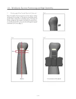
Страница 4: ...n the Dorsal surface of the positive cast fig 1 The position should be central to the midline of the wrist and elbow joints A distance of 30mm should be left between the Socket Terminal Dum my and the...
Страница 5: ...nuckle Assembly fig 4 The digit can now be freely disengaged from the Knuckle Assembly Fig 4 Fig 5 Fig 6 1 3 Extra Small and Medium Digit Assembly Depending on the size of the kit the Knuckle Mounting...
Страница 6: ...4 Knuckle Mounting Plate The Knuckle Mounting Plate will support 4 digits This Mounting Plate can be cut to suit the number of digits required for the user fig 7 Knuckle Mounting Modified Knuckle Moun...
Страница 7: ...ded for fixation of the plate to the frame fig 8 Take care not to over tighten screws Attach each digit using the supplied screws Screws are recommended to be single use 1 6 Attachment of the Digit to...
Страница 8: ...using three M2x5mm screws Depending on the handedness attach the thumb rotation assembly to the correct side of the alignment plate fig 11 using three M2x5mm screws 2 2 Knuckle Dummies Single knuckle...
Страница 9: ...9 of 25 Insert the Alignment Bars into the Single Knuckle Dum mies and lock each in place using M2 x 5mm Countersunk Torx Screw and the T6 Screwdriver fig 13 Fig 13...
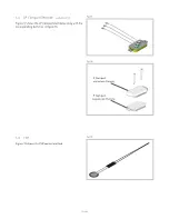
Страница 10: ...15 shows how the dome will look once fabricated into the silicone 3 2 Check Socket Electrodes During the check socket process the check socket elec trodes shown in figure 16 may be used This allows th...
Страница 11: ...lectrode available 2019 Figure 17 shows the LP Compact electrodes along with the corresponding dummies in figure 18 3 4 FSR Figure 19 shows the FSR control method LP Compact Lamination Dummy LP Compac...
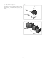
Страница 12: ...12 of 25 Fig 21 Fairing Knuckle Dummy 3 5 Knuckle Fairing Options Components for direct lamination are shown in figure 20 Components for non laminated fairings are shown in fig ure 21 Fig 20...
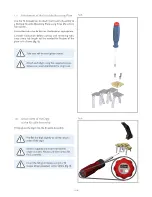
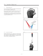
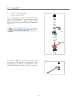
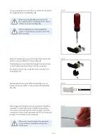
Страница 13: ...will now travel down through the centre of the spigot 4 1 Thumb Rotator Assembly Setting and Assembly The full thumb rotator assembly is illustrated fig 22 To increase the force required to rotate th...
Страница 14: ...x5mm Screws fig 24 Remove the knuckle cover from the thumb assembly by removing the two M2x4mm Screws fig 25 Remove the knuckle assembly from the thumb assembly by removing the M3 Grub Screw fig 26 Sc...
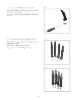
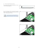
Страница 15: ...digit wires as shown Ensuring tooth is fully secured into connector fig 30 After diagnostic fitting thumb wire connector should be removed to enable fabrication of definitive prosthesis To remove con...
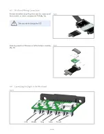
Страница 16: ...iddle Ring Little Fig 33 Fig 34 Slide the protective PCB cover out of the bellows assembly fig 33 4 4 Wristband Wiring Connections Remove the bellows by pulling them over the socket end of the assembl...
Страница 17: ...he digit wires through the aperture at the front of the bellows assembly fig 35 Fig 37 The digit wire connectors should be inserted into the bel low PCB A click should be felt when fully inserted Fig...
Страница 18: ...ires of the required digit Once the digit wires are connected slide the electrode ca bles through aperture shown in figure 41 Connect the cables following the mapping shown in figure 40 To mate the co...
Страница 19: ...as shown in figure 42 Fig 42 Check that there is no tension in the cables when flexed as shown in figure 43 similar to the digit wires approach as shown in figure 39 Before completion of the next sta...
Страница 20: ...be repositioned use the ex traction tool supplied fig 44 Insert the end portion of the tool under the connector flanges and pull off vertically in the direction of the con nector mating axis fig 45 a...
Страница 21: ...re at the socket end of the bellows Insert the pairs of wires as shown in figure 47 using the same method as inserting the digit wires Ensure click is heard indicating secure connection Removal of the...
Страница 22: ...wristband and remove the bellows assembly fig 48 Fig 48 Fig 49 Fig 50 Slide the bellows cover back into position over the bellows Bond the bellows cover to the bellows at either end using a few spots...
Страница 23: ...23 of 25 Attach the wristband to the socket using the M4 Socket Button Head Screw fig 51 and 52 Fig 51 Fig 52...
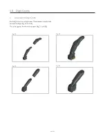
Страница 24: ...3 Fig 54 5 0 Digit Covers 5 1 Attaching the Digit Covers Each digit must use a digit cover These covers simply slide on over the digit fig 53 and 54 This also applies for the thumb cover fig 55 and 56...
Страница 25: ...3 Uppsala Sweden Tel 46 1818 2200 Fax 46 1818 2218 info ossur com ssur Iberia S L U Calle Cal ndula 93 Miniparc III Edificio E Despacho M18 28109 El Soto de la Moraleja Alcobendas Madrid Espa a Tel 00...