OSI OFS 2000C Скачать руководство пользователя страница 64

Optical Scientific Inc


OFS 2000CW User’s Guide 


P/N 1910-905 


Rev. 03/28/13 


57 

11.2 Control Enclosure Troubleshooting 

There are no user-serviceable parts in the Control enclosure. Information provided herein may be helpful when 
contacting OSI Technical Support. 
 
The Control/Interface Board and 
DSP (Digital Signal Processing) 
board have indicator LED’s which 
will show PCB activity and may 
help in isolating faults 

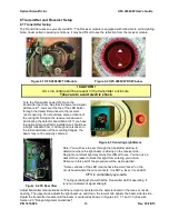
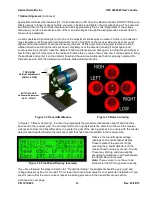
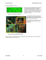
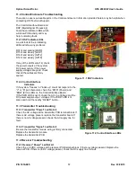
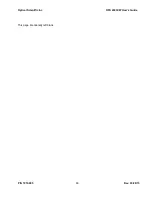
11.2.1 DSP lndicator LEDs  

A quick look at the 4 indicating 
LEDs will show any problems.  
 
D14 lit and pulsing [LED0] 
D15 lit and steady  [LED1] 
D16 lit and steady  [GP12] 
D19 lit and steady  [GP15] 
 
If any of the LED's aren't lit, check 
the power outputs at the system 
DC power supply. If the power 
supply voltages are good, check 
that all the cables are firmly 
seated. 
 

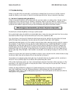
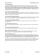
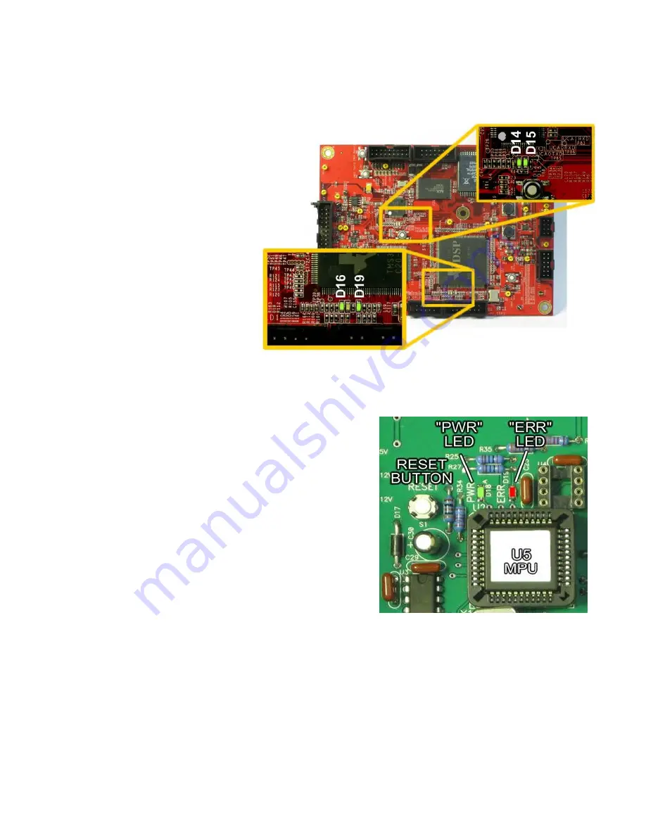
11.2.2 Control/Interface 

Indicators 

If the system “freezes” or “locks up” or will not respond to the 
“V” or “R” poll characters, check the “PWR” (Power) and 
“ERR” (Error) LEDs on the Control/Interface Board.  
If the PWR LED is not lit, check the AC Line Voltage and the 
DC power supply output  

voltages. If the “ERR” LED is lit, 

press and hold the nearby “RESET” button. 
 

11.3 Transmitter Troubleshooting 

11.3.1 Transmitter "Power" Led Not Lit  

Check the AC voltage at the transmitter PCB terminal block. If 
there is AC voltage present. replace the transmitter board. If 
there is no AC voltage present, check the AC supply line for 
fault.  
 

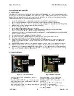
11.3.2 Transmitter "Signal" Led Not Lit  

Be sure the transmitter module wiring is firmly connected. 
Replace the transmitter module. 
Replace the transmitter PCB. 
 

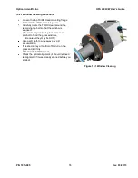
11.4 Receiver Troubleshooting 

11.4.1 Receiver "Power" Led Not Lit  

Check the +/- 8VDC voltages at the receiver PCB terminal block. If there is voltage present. Replace the 
receiver PCB. If there is no DC voltage present, check the DC supply line for fault.  


Figure 11.1 DSP Indicators 


Figure 11.2 Control/Interface LEDs 

Содержание OFS 2000C

Страница 1: ...FS 2000CW User s Guide P N 1910 905 User s Guide OFS 2000CW Optical Flow Sensor 03 28 13 OPTICAL SCIENTIFIC INC Tel 301 963 3630 Fax 301 948 4674 2 Metropolitan Ct Suite 6 Gaithersburg MD 20878 USA ww...

Страница 2: ...ription of Changes 11 29 2011 Production Release 04 11 2012 Added explanation for second current loop full scale 03 28 2013 Updated OFS 2000C User s Guide to create CW model User s Guide OFS 2000 Cert...

Страница 3: ...it Tubing Instructions 26 3 6 2 Pressurization Unit Set Up 26 3 6 3 Pressurization Unit Operation 27 3 7 AC Power Connections 28 3 7 1 Transmitter Unit 28 3 7 2 Control Box 28 3 8 User Interface Conne...

Страница 4: ...g 56 11 1 General Troubleshooting Guidelines 56 11 2 Control Enclosure Troubleshooting 57 11 2 1 DSP lndicator LEDs 57 11 2 2 Control Interface Indicators 57 11 3 Transmitter Troubleshooting 57 11 3 1...

Страница 5: ...tameter flow meter 21 Figure 3 8 Natural Air Purge 21 Figure 3 9 Compressed Air Purge 21 Figure 3 10 Purge Air at 90 to Vertical Flow 22 Figure 3 11 Rotameter Installation 22 Figure 3 12 Typical Gate...

Страница 6: ...e 6 4 TX Rear View 45 Figure 6 5 Receiver A B Lenses 46 Figure 6 6 Receiver LEDs and Flow Direction 46 Figure 7 1 Receiver Window Cat s Eyes 47 Figure 7 2 Transmitter Module 48 Figure 7 3 Beam Centeri...

Страница 7: ...oltages Disconnect AC power before servicing Optical Scientific Inc will not be held liable for any accident injury to personnel or damage to property incurred while operating or servicing this equipm...

Страница 8: ...LED in the transmitter emits a light beam which illuminates twin photodetectors in the receiver The received signal is amplified and sent to the Digital Signal Processor DSP in the Control Unit The r...

Страница 9: ...Optical Scientific Inc OFS 2000CW User s Guide P N 1910 905 Rev 03 28 13 2...

Страница 10: ...ture 40 to 60 C Dust Intrusion IP65 Moisture 0 100 condensing with dry purge air supplied Data Output Four 4 20 mA optical isolated outputs Loop 1 Velocity Loop 3 Temperature optional Loop 2 Volume Lo...

Страница 11: ...TX and RX units are supplied with integral spool piece flange adapters These adapters provide isolation and are equipped with 1 8 NPT purge air fittings to keep the light path clear The Control Box ho...

Страница 12: ...s clean The transmitter housing contains the transmitter optical assembly and transmitter driver circuit board The optical assembly is pre aligned in the factory and needs no focusing just aiming The...

Страница 13: ...and gaskets are supplied for installing the Transmitter and flange adapter on the customer s flange A silicone gasket is provided between the housing and the flange adapter to provide a weather tight...

Страница 14: ...ution for internal components and OFS Receiver TB1 connections for the Control Box to the RX Unit F TB2 connections for the fault relays and optional Calibration E TB3 connections for 4 20 mA current...

Страница 15: ...K Ground Lug User must connect to Earth ground L J5 DB9 RS 232 serial interface connector connects to J5 header on Control Interface PCB M J7 Remote display connector connects to J7 header on Control...

Страница 16: ...pressure sensor It connects to a filter fitting at the bottom of the control enclosure See Figure 1 8 This sensor provides an accurate high level analog output signal that is proportional to applied...

Страница 17: ...d at 1500W 120V It is recommended that a dedicated branch circuit controlled with a 15A breaker be provided The heater element is 3 4 in diameter 36 long with an INCONEL sheath and threaded to fit a 3...

Страница 18: ...meter leading upstream of the OFS and one times the pipe diameter trailing are good enough for OFS to make a representative flow measurement In some cases OFS 2000 units have been installed right at t...

Страница 19: ...ream from the heater A certain amount of shifting may be allowed for as not all sites are ideal but the critical parameter is the 8 centerline distance between the heater and the light path This shoul...

Страница 20: ...need to measure and know the path length for an OFS meter which is required for example when mounting an opacity meter Therefore in this regard mounting an OFS is simpler Alignment need not be microm...

Страница 21: ...the light beam off center The transmitted light beam will still reach the receiver and the system will work However the received signal will be weaker and performance will be compromised Note OFS uses...

Страница 22: ...e the flow is dampened somewhat by the stack interior surface Since this falls outside the RATA test area pipe protrusion should not pose a problem For example Figure 2 4 Measured Flow Cross Section I...

Страница 23: ...ch is nominally under the user s control Proper use of purge air is discussed in Section 3 4 Purge Air Figure 2 5 Flange Installation Incorrect Figure 2 6 Flange Installation Correct OFS 2000CW is des...

Страница 24: ...box 3 2 Required at Control Unit Location Instrument grade air at 2 CFM per head See notes in Sections 3 4 Purge Air and 3 6 Z Purge Air Single phase 100 240 VAC 1 A power with appropriately rated an...

Страница 25: ...hes for the TX RX head with Flange Adapter is shown in Figure 3 4 Figure 3 1 Common Vertical Installation Figure 3 2 Common Horizontal Installation Figure 3 3 OFS Mounting Hardware ITEM QTY DESCRIPTIO...

Страница 26: ...Optical Scientific Inc OFS 2000CW User s Guide P N 1910 905 Rev 03 28 13 19 Figure 3 4 OFS TX RX Overall Dimensions Units inches...

Страница 27: ...Box Mounting Dimensions Note Depth 6 3 8 inches The Control Box may be mounted to a wall or other surface with user supplied hardware It should be located within 15 feet of the RX Unit if the standar...

Страница 28: ...from misapplication and or lack of control it s use is not encouraged The use of Active Purge as described herein is recommended for optimum results Active Purge It is recommended the user apply instr...

Страница 29: ...ommon sense is encouraged The user should monitor window conditions and adjust purge air incrementally if needed until a balance is reached between affecting the system velocity readings and need for...

Страница 30: ...are available Consult OSI Engineering Department A typical installation is shown below Figure 3 12 Typical Gate Valve Installation Install a gate valve or similar shutoff device between the flange ada...

Страница 31: ...and practices OSI offers an equipment package which meets established North American requirements and has been found to work satisfactorily This package and recommended configuration is designed to pr...

Страница 32: ...TX and RX units and one for the control box Figure 3 15 Typical Z Purge Control Unit When the Z Purge option is ordered the OFS is shipped with vents and air fittings installed as shown in the figure...

Страница 33: ...r is closed and Protective Gas Supply is ON 2 Adjust Redundant Regulator if utilized to 5 psi maximum or skip to step 3 if enclosure is equipped with a Model PV 3 Purge Vent 3 Test Purge Vent if utili...

Страница 34: ...ization Unit Operation 1 Ensure Protected Enclosure Power is OFF Enclosure Pressure Control Regulator is closed Protective Gas Supply is ON and alarm system is activated if utilized 2 If utilized test...

Страница 35: ...tive earth wires must be green yellow in color and be of the same size gauge as the incoming mains supply conductors The Transmitter Board ground plane must be connected to the earth ground with a jum...

Страница 36: ...TB2 3 4 Cal Relay TB2 5 No Connection TB2 6 7 Ext Cal Switch connect See Section 3 13 for details Receiver Power and Signal I O TB1 1 2 12V rtn f heater TB1 3 4 8 8VDC RX power TB1 5 Signal Ground TB1...

Страница 37: ...t interface board The AGC Cable 1910 810 CW models carries a signal voltage to the Automatic Gain Control AGC circuitry on the transmitter driver board It connects directly to the circuit boards in bo...

Страница 38: ...ex 1910 217 XXX where 1910 217 BASIC ASSEMBLY NUMBER XXX CABLE LENGTH IN FEET Customers may opt to make their own cables If this is the case the following information is provided Cables should be 10...

Страница 39: ...s routed to the Sensor Interface Board in the Control Box where it is processed and sent to the DSP for integration into the system data 3 11 2 Activator Heater Interconnect The Activator Heater is eq...

Страница 40: ...connect wires that have a voltage on them to these terminals The maximum loop resistance is 600 ohms This includes the cable resistance and the load resistor in the customer data acquisition system Lo...

Страница 41: ...se when the system enters a calibration check cycle and open when the calibration check is finished 3 13 3 External Calibration Input Pins EARTH and EXT CAL IN are provided for the user to connect to...

Страница 42: ...tes a time stamp for every line of data so that events can be easily compared with process data The easiest way to ensure all data is collected is to set the main menu item described as Output Type to...

Страница 43: ...se may be left at default values select Windows Keys to use PC type keyboard input Click on the ASCII Setup button 5 The ASCII Setup window will open Select or deselect the following ASCII sending Sen...

Страница 44: ...Uppercase Characters Pressing the Enter key at any time will exit the Setup function Change commands will be acknowledged in two steps Erasing Save Buffer Done shows the change command has been accep...

Страница 45: ...tead of current loop Three output formats are available 0 Polled Default 1 Continuous Long Constant C poll output 2 Continuous Short Constant A poll output Polled is the normal operating mode for OFS...

Страница 46: ...able It is displayed to show the range and confirm the UOM 4 2 5 Correction Factor In some cases there will be a consistent difference high or low offset between the values reported by the OFS unit an...

Страница 47: ...from each period and determine an average flow figure This may and often does mean several days and nights of runs to gather a cohesive 3 point data sample Due to customer s operating necessities proc...

Страница 48: ...s 4 2 7 Duct Area Data The most basic element in volumetric calculations is the cross sectional area involved Formula for rectangular area Length X Width Area Formula for circular area x R 2 Area Wher...

Страница 49: ...mmended R Restart system Note all user set parameters are retained and a calibration check is performed V Displays firmware version installed Note All OFS poll commands are case sensitive Upper case i...

Страница 50: ...A A Fixed Field Detector A Signal Strength 14 Comma delimiter 15 18 Carrier Level aaaa Represents detector A carrier strength in volts from 0 10 to 9 99 volts 19 Comma delimiter 20 Detector B B Fixed...

Страница 51: ...are dashed out so that it does not cause fault condition 5 2 2 Description of Status Indicator Codes Bytes 29 32 Byte Unit of Measure Description Byte Averaging Time Description sec 29 0 m s 30 0 10 1...

Страница 52: ...tion from it Although care is taken in the initial installation of the mounting flanges the beam may not be properly centered Figure 6 3 Centering Light Beam Figure 6 4 TX Rear View Note You will have...

Страница 53: ...the locking screw on the right side of the mounting Place your finger on the top edge of the detector board Use your finger to rotate the board left or right until it is aligned with the direction of...

Страница 54: ...voltages should be within 30 of each other although If they are not within 30 re do the aim until they are By convention the A detector is the one that first sees the turbulence and is therefore the u...

Страница 55: ...oard and have some confidence that it is properly centered Do this exercise with both the Up Down and Side to Side adjustment knobs Figure 7 2 Transmitter Module Figure 7 3 Beam Centering In Figure 7...

Страница 56: ...Optical Scientific Inc OFS 2000CW User s Guide P N 1910 905 Rev 03 28 13 49...

Страница 57: ...harm to any components but will cause the A B voltage readings to max out and make it difficult to determine when the light beam is truly centered on the receiver module A temporary remedy for this is...

Страница 58: ...atch is good enough that we can be confident it was made by the same set of eddies and the velocity output will be within specifications Various factors may affect the shape match of the scintillation...

Страница 59: ...e unit of measure to the type preferred 11 Set the time constant to the longest time constant allowed Factory default is 1 minute 12 Set the current loop limit to the just above the highest flow rate...

Страница 60: ...or proper measurement Note The control box supplies DC power to the Receiver Figure 9 3 Control Enclosure Display Look inside the Control Enclosure and see that the LEDs on the Control Interface and D...

Страница 61: ...when you have to diagnose a problem which has appeared and you want to compare with the way it used to look Biannually or when cleaning windows Installation condition check Inspect the TX Head RX Head...

Страница 62: ...e remaining top bolt so that the window is exposed Use commonly available glass cleaner or alcohol to flood the glass windows Be careful they may be HOT Use a soft cloth to wipe away any dirt accumula...

Страница 63: ...t buildup Sometimes stack duct gases cool in the nozzles and spool pieces and create fog and mist which can weaken the correlation To see if mist is forming keep the heads installed and use a small br...

Страница 64: ...eezes or locks up or will not respond to the V or R poll characters check the PWR Power and ERR Error LEDs on the Control Interface Board If the PWR LED is not lit check the AC Line Voltage and the DC...

Страница 65: ...Signal Led Not Lit Be sure the transmitter is transmitting Be sure the light beam path is unobstructed and the windows are clear Check alignment as shown previously in this document Be sure the recei...

Страница 66: ...3 Fault 3 Input Voltage Out of Range This message indicates a problem with the DC power supply Check the 5 12 12 VDC voltages are at acceptable levels 11 5 4 Fault 5 Heating Activity Error Byte 31 cod...

Страница 67: ...5 1 4 Window Retaining Ring w Gaskets Screws p n 1910 808 5 Control Interface DSP PCB p n 1910 311 1 6 Digital Signal Processor DSP PCB p n 2827 312 12 2 Available Spare Parts Unit Sub Assembly P N TX...

Страница 68: ...t It is possible that during periodic cleaning or maintenance of the TX and RX Units the alignment can be disturbed In a well aligned installation the effect of movement is negligible In a marginally...

Страница 69: ...ion setting Otherwise a simple scheduled calibration cycle is adequate The thing to remember is that the OFS calibrates itself to an internal reference completely ignoring whatever is being currently...

Страница 70: ...Optical Scientific Inc OFS 2000CW User s Guide P N 1910 905 Rev 03 28 13 63 This page intentionally left blank...

Отзывы: