background image

SECTION 4 - MACHINE OPERATION

4-6

– JLG Lift –

3121252

4.3 MOTOR OPERATION

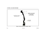
Power/Emergency Stop Switch

This red, mushroom-shaped switch provides battery power
to the Platform/Ground Select switch, when pulled out (on),
for all machine functions. The switch should be pushed in
(off) when recharging the batteries or parking the machine
overnight. 

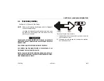
Platform/Ground Select Switch

The Platform/Ground Select switch functions to direct battery
power to the desired control station when the POWER/
EMERGENCY STOP switch is pulled out (on). With the
switch in the GROUND position, battery power is supplied to
the ground control station. When the switch is in the PLAT-
FORM position, battery power is supplied to the platform
control station. 

The key is removable in the platform position on CE
machines. The key must be available to ground personnel in
the event of an emergency.
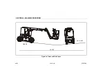
Motor Activation

FOOTSWITCH MUST BE DEPRESSED PRIOR TO ACTIVATING ANY FUNC-
TION, OTHERWISE FUNCTION WILL NOT OPERATE. 

The motor becomes activated and operates the desired
function when the Emergency Stop switch is pulled out (on),
the Platform/Ground select switch is in the appropriate posi-
tion and the Footswitch is depressed. 

IF A MOTOR MALFUNCTION NECESSITATES UNSCHEDULED SHUT-
DOWN, DETERMINE AND CORRECT THE CAUSE BEFORE RESUMING
ANY OPERATION. 

ALWAYS POSITION EMERGENCY STOP SWITCH TO THE ‘OFF’ POSI-
TION (PUSHED IN) WHEN MACHINE IS NOT IN USE. 

Содержание JLG E300AJ

Страница 1: ...Operation and Safety Manual ANSI Original Instructions Keep this manual with the machine at all times Boom Lift Models E300AJ E300AJP S N 0300138358 to Present 3121252 August 9 2012...

Страница 2: ......

Страница 3: ...owners users operators lessors and lessees with the precautions and operating procedures essential for the safe and proper machine operation for its intended purpose Due to continuous product improve...

Страница 4: ...L HAVE AN ORANGE BACKGROUND INDICATES A POTENTIALLY HAZARDOUS SITUATION IF NOT AVOIDED MAY RESULT IN MINOR OR MODERATE INJURY IT MAY ALSO ALERT AGAINST UNSAFE PRACTICES THIS DECAL WILL HAVE A YELLOW B...

Страница 5: ...S HAVE BEEN INVOLVED IN AN ACCIDENT INVOLVING BODILY INJURY OR DEATH OF PERSONNEL OR WHEN SUBSTANTIAL DAMAGE HAS OCCURRED TO PERSONAL PROP ERTY OR THE JLG PRODUCT Contact Product Safety and Reliabilit...

Страница 6: ...D d JLG Lift 3121252 REVISION LOG Original Issue June 26 2009 Revised September 29 2009 Revised October 28 2009 Revised November 19 2009 Revised November 8 2010 Revised February 6 2012 Revised August...

Страница 7: ...2 1 Operator Training 2 1 Training Supervision 2 1 Operator Responsibility 2 1 2 2 PREPARATION INSPECTION AND MAINTENANCE 2 2 Pre Start Inspection 2 4 Function Check 2 5 General 2 9 SECTION 3 MACHINE...

Страница 8: ...ATIONS OPERATOR MAINTENANCE 6 1 INTRODUCTION 6 1 6 2 OPERATING SPECIFICATIONS AND PERFORMANCE DATA 6 1 Operating Specifications 6 1 Dimensional Data 6 2 Capacities 6 3 Tires 6 3 Hydraulic Oil 6 4 Majo...

Страница 9: ...ecal Location Sheet 5 of 5 4 18 5 1 Manual Descent Location 5 3 6 1 Operator Maintenance and Lubrication Diagram 6 8 LIST OF TABLES 1 1 Minimum Approach Distances M A D 1 5 1 2 Beaufort Scale For Refe...

Страница 10: ...TABLE OF CONTENTS iv JLG Lift 3121252 SECTION PARAGRAPH SUBJECT PAGE SECTION PARAGRAPH SUBJECT PAGE This page left blank intentionally...

Страница 11: ...machine should not operate the machine until this manual has been read training is accomplished and operation of the machine has been completed under the supervision of an experi enced and qualified...

Страница 12: ...iting by JLG Do not operate the machine in hazardous environments unless approved for that purpose by JLG Be sure that the ground conditions are able to support the maximum load shown on the decals lo...

Страница 13: ...orm the opera tor shall be responsible for all machine operations Always ensure that power tools are properly stowed and never left hanging by their cord from the platform work area Supplies or tools...

Страница 14: ...se the boom assembly to enter or leave the plat form Use extreme caution when entering or leaving platform Be sure that the boom is fully lowered It may be neces sary to telescope out to position the...

Страница 15: ...d its occupants their tools and their equipment from any electrical line or apparatus carrying up to 50 000 volts One foot additional clearance is required for every additional 30 000 volts or less Ta...

Страница 16: ...uced to a distance within the designed working dimensions of the insulating barrier This determination shall be made by a qualified per son in accordance with the employer local or governmental requir...

Страница 17: ...e Do not tie off machine to any adjacent structure Do not operate the machine when wind conditions exceed 28 mph 12 5 m s Refer to Table 1 2 Beaufort Scale For Reference Only Do not increase the surfa...

Страница 18: ...from striking or interfering with operating controls and per sons in the platform Be sure that operators of other overhead and floor level machines are aware of the aerial work platform s pres ence Di...

Страница 19: ...rforming welding or metal cutting operations precautions must be taken to protect the chassis from direct exposure to weld and metal cutting spatter Do not refuel the machine with the engine running B...

Страница 20: ...eltonexposedskin Leavesrustle 3 8 12 3 4 5 4 Gentle breeze Leavesandsmaller twigsin constantmotion 4 13 18 5 5 7 9 Moderate breeze Dustand loose paper raised Small branchesbegin tomove 5 19 24 8 0 10...

Страница 21: ...the employer and government regulations 4 Use of approved fall protection device 5 Enough knowledge of the mechanical operation of the machine to recognize a malfunction or potential mal function 6 T...

Страница 22: ...ons for further requirements for aerial work plat forms The frequency of inspections and maintenance must be increased as necessary when the machine is used in a harsh or hostile environment if the ma...

Страница 23: ...pection SeeNote Inservicefor3monthsor150hours whichever comes first or Outofserviceforaperiodofmorethan3months or Purchasedused Owner Dealer or User Qualified JLG Mechanic ServiceandMaintenance Manual...

Страница 24: ...e decals and placards are missing Make sure all illegible decals and placards are cleaned or replaced 4 Operation and Safety Manuals Make sure a copy of the Operator and Safety Manual AEM Safety Manua...

Страница 25: ...FF THE MACHINE IMMEDIATELY REPORT THE PROBLEM TO THE PROPER MAINTENANCE PERSONNEL DO NOT OPERATE THE MACHINE UNTIL IT IS DECLARED SAFE FOR OPERATION Function Check Perform the Function Check as follow...

Страница 26: ...ns are disabled when the Emergency Stop Button is pushed in e Ensure that all machine functions stop when the footswitch is released 3 With the platform in the stowed position a Drive the machine on a...

Страница 27: ...Lift 2 7 1 2 3 4 5 6 7 8 9 10 11 12 13 14 Figure 2 1 Basic Nomenclature 1 Platform 2 PlatformConsole 3 JibRotator E300AJPOnly 4 BoomFlySection 5 MainBoom 6 Turntable 7 Counterweight 8 Non DriveHub 9 B...

Страница 28: ...ECTION 2 USER RESPONSIBILITIES MACHINE PREPARATION AND INSPECTION 2 8 JLG Lift 3121252 1 2 12 8 13 3 5 6 4 14 7 11 8 10 5 8 5 10 15 9 2 16 7 14 6 5 Figure 2 2 Daily Walk Around Inspection Sheet 1 of 3...

Страница 29: ...r blocked Latch and hinges in working condition 2 Platform Ground Control Consoles Switches and levers return to neutral decals placards secure and legible control markings legible 3 Boom Sections Upr...

Страница 30: ...See Inspection Note 12 Platform Rotator See Inspection Note 13 Jib Rotator See Inspection Note 14 Battery Compartment Batteries have proper elec trolyte level cables tight see Inspection Note 15 Coun...

Страница 31: ...by the ground controls for these sym bols and the corresponding functions NOTE The indicator panels use different shaped symbols to alert the operator to different types of operational situations that...

Страница 32: ...Function Enable switch must be held down in order to operate Boom Telescope Lower Lift Swing Main Lift Jib Lift Platform Level Override and Platform Rotate functions 1 Battery Charge Status Three LED...

Страница 33: ...1 12 13 14 Figure 3 1 Ground Control Station E300AJ 1 BatteryChargeStatus 2 FunctionEnable 3 MainBoomLift 4 LowerBoomLift 5 Swing 6 Platform Ground Select 7 Power Emergency Stop 8 Telescope 9 JibLift...

Страница 34: ...10 11 12 13 14 1 BatteryChargeStatus 2 FunctionEnable 3 MainLift 4 LowerLift 5 Swing 6 Platform Ground Select 7 Power Emergency Stop 8 Telescope 9 JibLift 10 JibSwing 11 PlatformLevel 12 PlatformRotat...

Страница 35: ...three position key operated switch supplies power to the platform control console when positioned to PLATFORM With the switch key turned to the GROUND position power is shut off to platform and only g...

Страница 36: ...INJURY 11 Platform Leveling Override A three position switch allows the operator to adjust the automatic self leveling system This switch is used to adjust platform level in situations such as ascend...

Страница 37: ...tion Posi trac will be engaged for approximately 20 seconds ONLY USE THE PLATFORM LEVELING OVERRIDE FUNCTION FOR SLIGHT LEVELING OF THE PLATFORM INCORRECT USE COULD CAUSE THE LOAD OCCUPANTS TO SHIFT O...

Страница 38: ...566 B 1704422 A 1 2 3 4 5 6 7 8 9 10 11 13 12 1 Posi Track 2 PlatformLevelingOverride 3 Horn 4 Power EmergencyStop 5 DriveOrientationOverride 6 Drive Steer 7 Telescope 8 Jib 9 JibSwing 10 LowerBoomLif...

Страница 39: ...spring loaded and will automatically return to neutral off position when released 6 Drive Steer Push forward to drive forward pull back to drive in reverse Steering is accomplished via a thumb activa...

Страница 40: ...Main Boom Lift Swing joystick pull up on the locking ring below the handle NOTE The Main Boom Lift Swing joystick is spring loaded and will automatically return to neutral off position when released...

Страница 41: ...ontal and the machine is on a slope the tilt alarm warning light will illuminate and an alarm will sound and CREEP is automatically activated IF TILT WARNING LIGHT IS ILLUMINATED WHEN BOOM IS RAISED O...

Страница 42: ...imum power limit has been reached and the machine is not moving This could happen when the machine is stuck or when attempting to travel over rough terrain or on steep grades which exceed the rated gr...

Страница 43: ...shows that the controls are enabled If a function is not selected within seven sec onds or if a seven second lapse between ending one function and beginning the next function the enable light will go...

Страница 44: ...SECTION 3 MACHINE CONTROLS AND INDICATORS 3 14 JLG Lift 3121252 NOTES...

Страница 45: ...control station the operator can drive and steer the machine in both forward and reverse directions The opera tor can raise or lower the boom or swing the boom to the left or right Standard boom swing...

Страница 46: ...acturers rated design capacity 3 All machine systems are functioning properly 4 Machine is as originally equipped from JLG Stability Machine stability is based on two 2 conditions which are called FOR...

Страница 47: ...ON 3121252 JLG Lift 4 3 Figure 4 1 Position of Least Forward Stability LOWERBOOM FULLYELEVATED MAINBOOM HORIZONTAL MAINBOOM FULLY EXTENDED MACHINEWILL TIPOVER INTHIS DIRECTIONIFOVERLOADED OR OPERATED...

Страница 48: ...4 4 JLG Lift 3121252 Figure 4 2 Position of Least Backward Stability E300AJ LOWERBOOM FULLYELEVATED MAINBOOM FULLYELEVATED ANDFULLYRETRACTED MACHINEWILL TIPOVER INTHIS DIRECTIONIFOVERLOADED OR OPERAT...

Страница 49: ...ift 4 5 Figure 4 3 Position of Least Backward Stability E300AJP LOWERBOOM FULLYELEVATED PLATFORMROTATED 90DEGREES MAINBOOM FULLYELEVATED ANDFULLYRETRACTED MACHINEWILL TIPOVER INTHIS DIRECTIONIFOVERLOA...

Страница 50: ...control station When the switch is in the PLAT FORM position battery power is supplied to the platform control station The key is removable in the platform position on CE machines The key must be avai...

Страница 51: ...OVER DO NOT DRIVE MACHINE ON GRADES EXCEEDING THOSE SPECIFIED ON THE SERIAL NUMBER PLATE DO NOT DRIVE ON SIDESLOPES WHICH EXCEED 5 DEGREES USE EXTREME CAUTION WHEN DRIVING IN REVERSE AND AT ALL TIMES...

Страница 52: ...SECTION 4 MACHINE OPERATION 4 8 JLG Lift 3121252 GRADE LEVEL SIDE SLOPE Figure 4 4 Grade and Side Slopes...

Страница 53: ...ase the Drive Orientation Override switch Within 3 seconds slowly move the Drive control toward the arrow matching the intended direction of machine travel The indicator light will flash during the 3...

Страница 54: ...LEVATED TO AVOID TIP OVER IF RED TILT WARNING LIGHT LIGHTS WHEN BOOM IS RAISED ABOVE HORIZONTAL LOWER PLATFORM TO GROUND LEVEL THEN REPOSITION MACHINE SO THAT CHASSIS IS LEVEL BEFORE RAISING BOOM TRAV...

Страница 55: ...Telescope and Swing When in the fully counterclockwise position Drive is placed in creep speed 4 9 SHUT DOWN AND PARK NOTE When parking battery powered units overnight batteries should be charged in a...

Страница 56: ...Refer to the Serial Number Plate refer to the Specifica tions section of this manual or weigh the individual unit to find out the Gross Vehicle Weight 2 Place the boom in the stowed position 3 Remove...

Страница 57: ...SECTION 4 MACHINE OPERATION 3121252 JLG Lift 4 13 A 41 4 1 04m B 44 0 1 11m E300AJ AJP 1001112461B A B Figure 4 5 Lifting and Tie Down Chart...

Страница 58: ...SECTION 4 MACHINE OPERATION 4 14 JLG Lift 3121252 BOTH SIDES BOTH SIDES BOTH SIDES HYD TANK VIEW INSIDE HOOD 7 24 25 26 30 14 19 9 6 28 Figure 4 6 Decal Location Sheet 1 of 5...

Страница 59: ...SECTION 4 MACHINE OPERATION 3121252 JLG Lift 4 15 46 33 6 14 23 24 23 16 45 29 31 24 15 5 36 Figure 4 7 Decal Location Sheet 2 of 5...

Страница 60: ...SECTION 4 MACHINE OPERATION 4 16 JLG Lift 3121252 11 22 32 34 25 25 26 12 9 42 40 41 Figure 4 8 Decal Location Sheet 3 of 5...

Страница 61: ...SECTION 4 MACHINE OPERATION 3121252 JLG Lift 4 17 44 46 SEE DETAIL A DETAIL A 3 4 8 20 29 21 12 18 39 43 45 20 17 23 23 33 27 2 35 37 1 37 Figure 4 9 Decal Location Sheet 4 of 5...

Страница 62: ...SECTION 4 MACHINE OPERATION 4 18 JLG Lift 3121252 BOTH SIDES LOCATE ON SIDE OF CONTROL BOX 13 13 30 9 10 38 Figure 4 10 Decal Location Sheet 5 of 5...

Страница 63: ...8 1701509 1701509 1701509 1701509 1701509 1701509 1701509 1701509 9 1701529 1701529 1701529 1701529 1701529 1701529 1701529 1701529 10 1701642 1701642 1701642 1701642 1701642 1701642 1701642 1701642...

Страница 64: ...04277 1704277 1704277 1704277 1704277 28 1704412 1704412 1704412 1704412 1704412 1704412 1704412 1704412 29 30 1706126 1706126 1706126 1706126 1706126 1706126 1706126 1706126 31 32 1707013 1707054 170...

Страница 65: ...1001112461 42 1001112777 1001112777 1001112777 1001112777 1001112777 1001112777 1001112777 1001112777 43 1705351 1705426 1705427 1705910 1705429 1705430 1001113680 44 1705828 1703980 1703981 1703983 1...

Страница 66: ...SECTION 4 MACHINE OPERATION 4 22 JLG Lift 3121252 NOTES...

Страница 67: ...within 48 hours of such an occur rence may void any warranty consideration on that particular machine FOLLOWING ANY INCIDENT THOROUGHLY INSPECT THE MACHINE AND TEST ALL FUNCTIONS FIRST FROM THE GROUN...

Страница 68: ...both drive hubs by loosening completely reversing and tightening the two bolts on each hub 4 Remove chocks from wheels as desired 5 5 MANUAL DESCENT SYSTEM See Figure 5 1 Manual Descent Location The...

Страница 69: ...SECTION 5 EMERGENCY PROCEDURES 3121252 JLG Lift 5 3 Figure 5 1 Manual Descent Location SPLITRING MANUAL DESCENTKNOB...

Страница 70: ...and turntable assembly in the event of a total power failure when the platform is positioned over a structure or obstacle To oper ate the manual swing override proceed as follows 1 Using a 7 8 inch so...

Страница 71: ...le included in the Service and Maintenance Manual Other Publications Available Service and Maintenance Manual 3121253 Illustrated Parts Manual 3121254 6 2 OPERATING SPECIFICATIONS AND PERFORMANCE DATA...

Страница 72: ...3mph 4 8kph DriveSpeed AboveHorz 50ft 15 24M 55 68 sec 0 6mph 0 9kph GrossMachineWeight Approximate 15400lbs 6985kg Ground BearingPressure Maximum 170psi 11 95kg cm2 MaximumSystem Voltage 48VDC Maximu...

Страница 73: ...th stowed 18ft 10in 5 74m UpandOverPlatformHeight 13ft 2in 4 01m Horizontal ReachUpandOver 20ft 1in 6 12m MachineWidth 4ft 1 22m Wheel Base 5ft 5in 1 65m PlatformHeight 29ft 5in 8 97m GroundClearance...

Страница 74: ...cSt at 40 C and viscosity index of 213 The oper ating temperature range of this oil is 18 C to 83 C NOTE Aside from JLG recommendations it is not advisable to mix oils of different brands or types as...

Страница 75: ...C Viscosity Brookfield cP at 18 C 2700 at40 C 55cSt at 100 C 9 3cSt ViscosityIndex 152 Table 6 10 Mobil EAL 224H Specs Type Biodegradable Vegetable Oil ISOViscosityGrade 32 46 Specific Gravity 922 Po...

Страница 76: ...y 950 PourPoint Max 59 F 51 C Flash Point Min 514 F 268 C Viscosity at40 C 33 1cSt at 100 C 6 36cSt ViscosityIndex 147 Table 6 12 Quintolubric 888 46 Density 0 91 15 C 59 F PourPoint 20 C 4 F FlashPoi...

Страница 77: ...ERENT WEIGHT OR SPECIFICATION FOR EXAMPLE BATTERIES FILLED TIRES PLATFORM DO NOT MODIFY UNIT IN ANY WAY TO AFFECT STABILITY Table 6 13 Critical Stability Weights Components LBS KG Counterweight AJ 618...

Страница 78: ...SECTION 6 GENERAL SPECIFICATIONS OPERATOR MAINTENANCE 6 8 JLG Lift 3121252 1 5 6 3 4 2 6 5 Figure 6 1 Operator Maintenance and Lubrication Diagram...

Страница 79: ...ote Fitting Capacity A R Lube BG Interval Every 3 months or 150 hrs of operation Comments Apply grease and rotate in 90 degree intervals until bearing is completely lubricated Table 6 14 Lubrication S...

Страница 80: ...21252 2 Swing Bearing Worm Gear Teeth Lube Point s Grease Fitting Capacity A R Lube BG Interval A R Lube Point s Grease Fitting Capacity A R Lube Mobile SHC 007 Interval A R DO NOT OVERGREASE BEARINGS...

Страница 81: ...rs or 1200 hours of operation Comments On new machines those recently over hauled or after changing hydraulic oil operate all systems a minimum of two complete cycles and recheck oil level in reservoi...

Страница 82: ...s Level Fill Plug Capacity 25 5 oz 0 75 L 1 2 Full Lube EPGL Interval Check level every 3 months or 150 hrs of opera tion change every 2 years or 1200 hours of operation 6 Wheel Bearings Lube Point s...

Страница 83: ...harging When adding water to the battery fill only to level indi cated or 3 8 9 5 mm above separators 2 Remove all vent caps and inspect electrolyte level of each cell Electrolyte level should be to t...

Страница 84: ...2 Charge batteries in accordance with the following proce dure a Open battery compartment and battery charger compartment covers WHEN BATTERY CHARGER IS TO BE USED CHARGING HARNESS MUST BE PLUGGED INT...

Страница 85: ...recommended by JLG Due to size variations between tire brands both tires on the same axle should be the same Wheel and Tire Replacement The rims installed on each product model have been designed for...

Страница 86: ...ation is provided in accordance with the requirements of the European Machinery Directive 2006 42 EC and is only applicable to CE machines For electric powered machines the equivalent continuous A Wei...

Страница 87: ...CTION 7 INSPECTION AND REPAIR LOG 3121252 JLG Lift 7 1 SECTION 7 INSPECTION AND REPAIR LOG MachineSerial Number _______________________________________ Table 7 1 Inspection and Repair Log Date Comment...

Страница 88: ...SECTION 7 INSPECTION AND REPAIR LOG 7 2 JLG Lift 3121252 Table 7 1 Inspection and Repair Log Date Comments...

Страница 89: ...rented units should not be included on this form Mfg Model _______________________________________________________________ Serial Number ____________________________________________________________ P...

Страница 90: ......

Страница 91: ......

Страница 92: ...53 88 31 70 33 0 5 53 88 31 79 JLG Deutschland GmbH Max Planck Str 21 D 27721 Ritterhude Ihlpohl Germany 49 0 421 69 350 20 49 0 421 69 350 45 JLG Equipment Services Ltd Rm 1107 Landmark North 39 Lun...

Отзывы: