OSF 3104811211 Скачать руководство пользователя страница 3

Operating instructions EUROTRONIK-20    Page: 3 


Mounting 

The controller must be mounted in accordance with its system of protection so that it is protected against 
moisture.  The  ambient  temperature  should  lie  between  0°  C  and  +  40°  C  and  should  be  as  constant  as 
possible.  The  relative  humidity  should  not  exceed  95%  and  no  condensation  should  occur.  Direct 
incidence of heat or sunlight on the device must be avoided. 

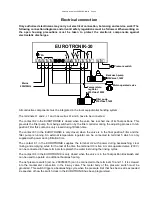
The power supply to the device must be connected via an all-polar main switch with a contact gap width of 
at least 3mm. 

The device must be switched off before the housing is opened. 

Preparation of the 6-way valve 

Before  mounting  the  EUROTRONIK  it  must  be  ensured  that  the 
valve moves easily and is free of dirt. 

The 6-way valve must be in the position Filter when mounting 
the  controller.

  In  this  position  the  handle  of  the  valve  must  be 

removed  by  driving  the  fastening  pin  out  of  the  valve  shaft.  Then 
insert the shorter osf pin delivered with the device in the middle of 
the hole in the valve shaft. If the pin is too loose in the hole, it can 
be fastened with a little adhesive or grease to facilitate mounting of 
the  controller.  For  later  operation  of  the  system  it  is  immaterial 
whether the pin is loose because it is centred by the housing of the 
controller. 

Preparation of the controller 

The controller must be in the position 

Filter

 (position on delivery). 

To equalise height differences of the valve shafts, it is necessary in the case of some valves to stick one 
or more of the self-adhesive spacer disks delivered with the device under the housing of the controller. 

Proceed as follows to determine whether one or more spacer disks are needed: 

Move the 6-way valve into the position 

Filter

Mount  the  EUROTRONIK-10  on  the  valve  without  spacer  disk. 
See "Mounting of the EUROTRONIK". 

Push  the  feeler  gauge  delivered  with  the  device  between  the 
EUROTRONIK and valve. 

If  the  feeler  gauge  fits  between  the  EUROTRONIK  and  valve 
exactly, the gap is optimal. 

If  the  EUROTRONIK  wobbles  on  the  valve,  one  or  more  spacer 
disks must be stuck under the EUROTRONIK (see sketch below). 

Thereafter  the  EUROTRONIK  must  be  mounted  again  and  the 
test with the feeler gauge repeated. 

After mounting the feeler gauge has to be removed. The resultant 
play has no negative influence on the operation of the system. 


Insert
feeler

gauge


Shorter osf-pin

Guide groove


Содержание 3104811211

Страница 1: ...ump backwash pump or blower A connection for an external temperature regulator provides the possibility of heating the pool during the filtration times An internal latch makes sure that the heater wil...

Страница 2: ...ntroller on off 7 Manual control of the filter pump 7 Setting the time 7 Programming the timer backwashing and clear rinsing times 8 Programming the timer filtration times 8 Backwashing manual 9 Empty...

Страница 3: ...little adhesive or grease to facilitate mounting of the controller For later operation of the system it is immaterial whether the pin is loose because it is centred by the housing of the controller Pr...

Страница 4: ...ral Valve with bayonet lock Replace slides if necessary Stick on spacer disks if necessary Mounting of the EUROTRONIK Press the two slides yellow or red in completely at the same time Place the contro...

Страница 5: ...ocess In teh position Filter this contact is only closed during filtration time The contact K3 in the EUROTRONIK is only closed when the valve is in the final position Filter and the filter pump is ru...

Страница 6: ...is first lifted Rotate Backwash The valve disk is turned into the position Backwash Lower Backwash The valve disk is lowered into the position Backwash 4 39 Backwash The backwashing cycle is running T...

Страница 7: ...ff The EUROTRONIK is off The valve is in the position Filter Switch defect The bottom final position of the valve disk has not been detected The microswitch in the bottom part of the housing is possib...

Страница 8: ...and the normal operating display appears again If backwashing times have already been programmed they can be deleted with the key 1 Press the key repeatedly until the backwashing time that is to be d...

Страница 9: ...ycle is the same as that entered during programming of the timer This key can also be used to end a backwashing cycle already in progress Emptying the swimming pool When the key is pressed for longer...

Страница 10: ...ation of the filter pump during the complete backwashing time b Intermittent backwashing with repeated switching on and off of the pump during the backwashing time for better loosening of the filter s...

Страница 11: ...essure switch Switch status of a pressure switch connected to terminals 10 and 11 B fortnightly Switch position of the left DIP switch backwash fortnightly B interval Switch position of the right DIP...

Страница 12: ...with the help of the contact K4 The following displays are possible Backw pump OFF The pump is off K4 open Backw pump ON The pump is on K4 closed When the auxiliary backwash pump is shown in the top...

Страница 13: ...ff when the bottom final position is reached or the key is pressed again 4 The normal diagnostics display reappears when the key is pressed again Note The drain of the swimming pool must be installed...

Страница 14: ......

Отзывы: