background image

Functionality of the Main Menu


36


shown in Figure 5.1-5: 

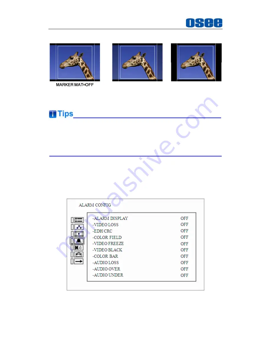
MARKER MAT=HALF

MARKER MAT=BLACK


Figure 5.1-5    MARKER MAT 


  All markers will be hidden in the following modes though the corresponding 

marker is enabled (the value is not OFF): NATIVE. 

  The safety marker area will change with the area marker. 


5.1.4

 ALARM CONFIG Menu 

The Alarm Config Menu items are used to adjust the parameters displayed 
on the screen, the menu items are as shown in Figure 5.1-6: 


Figure 5.1-6  Alarm Config Menu 

The relationship of Items, Default Value, Domain Range and Description 

Содержание MVM-170 Series

Страница 1: ...MVM 170 MVM 200 Series Quad Split LCD Monitor User Manual...

Страница 2: ......

Страница 3: ...V010100 Release Date September 27th 2016 Company OSEE TECHNOLOGY CO LTD Contact Information Address No 22 Building No 68 zone Beiqing Road Haidian District Beijing China Post Code 100094 Tel 86 010 6...

Страница 4: ...o when using this product Contents The user manual applies to the following device types MVM 170 3HSV MVM 170 HSV MVM 170 SV MVM 200 3HSV MVM 200 HSV MVM 200 SV The above listed devices have most simi...

Страница 5: ...1 3 Display Mode 20 4 2 Rear Panel Features 23 4 2 1 Arrangement of Rear Panel 23 4 2 2 Operations of Rear Panel 24 4 3 Supported Signal Format 26 Chapter 5 Functionality of the Main Menu 29 5 1 Main...

Страница 6: ......

Страница 7: ...achieve the best possible image display Each display screen of the monitor is an independent professional monitor So it can achieve the various professional parameters and can be adjusted independentl...

Страница 8: ...tor Support the independent adjustment of the parameters for single screen With all the important functions of multi view processor Support high quality waveform vector monitoring Support HDMI output...

Страница 9: ...ainst harmful interference in a residential installation This equipment generates uses and can radiate radio frequency energy and if not installed and used in accordance with the instructions may caus...

Страница 10: ...qualified service personnel Servicing will be required under all of the following conditions The unit has been exposed to rain or moisture Liquid had been spilled or objects have fallen onto the unit...

Страница 11: ...ord or bend the power cord Protect the power cord from being walked on or pinched particularly at plugs convenience receptacles and the point where they exit from the unit If the power cord is damaged...

Страница 12: ...6...

Страница 13: ...nual 1 4 The electric accessory 19V adapter 1 Power cord 1 Installation 1 Prepare for installation Please follow the procedures below before installing MVM 200 Check the equipment for any invisible da...

Страница 14: ...tor are packaged separately Connect a standard signal line to the corresponding input port All BNC connector impedance must be 75 Please use the power cord supplied to avoid unnecessary trouble and ma...

Страница 15: ...rear panel of the monitor fasten them then mount the monitor onto the cabinet steadily and firmly Buckle the monitor with the hanger at the right top of the monitor on the rear panel to lock the monit...

Страница 16: ...m then mount the monitor onto the videowall frame steadily and firmly Buckle the monitor with the hanger at the right top of the monitor on the rear panel to lock the monitor in case of unexpected rol...

Страница 17: ...first insert the FPC line of the monitor to the corresponding slot of the extra control buttons bar as shown in the following illustration Figure 3 5 FPC Connection Step 2 second mount the extra contr...

Страница 18: ...nt the Kit of the Extra Control Buttons Bar Step 3 at last connect the extra control buttons bar to the monitor with the pan head screws fasten them firmly as shown in the following illustration Figur...

Страница 19: ...2 Audio Meter It is displayed for audio monitoring You can set its parameters in AUDIO CONFIG menu It could be semi transparent displayed which will reduce the impact for the image 3 Waveform and Vec...

Страница 20: ...indow and the color could be changed according to the designated color red green yellow white You can set its parameters in OSD CONFIG menu 7 IMD The IMD text displays at the bottom of the screen the...

Страница 21: ...lays only for CH1 and CH3 in the screen Each channel is corresponding to a display window You can see the Waveform and vector of CH1 is displayed in No 2 Window and the Waveform and vector of CH3 is d...

Страница 22: ...t will introduce the arrangement and the operations of the buttons in front of the panel in the following 4 1 1 Arrangement of Front Panel There are a series of buttons at the bottom of the screen and...

Страница 23: ...tch from quad split screen display to CH1 full screen display Select CH1 when in quad split screen display mode press MENU button to display the main menu in the center of the screen then press CH1 bu...

Страница 24: ...Main menu Refer to 5 2 Menu Settings for detail about the main menu operations After you have loaded the function menu list it will be closed automatically if you do nothing operation with it in 5s I...

Страница 25: ...e the following functions Enter into the next level menu press ENTER button you will enter into the menu item as this relationship the Main menu list sub menu list sub menu value list the current edit...

Страница 26: ...n with it in 5s The main menu the adjust menu the function menu and the input signal selection list of a screen may not be shown all simultaneously 11 Power Used to power on or standby and the light i...

Страница 27: ...play mode The whole screen is divided into four windows in QUAD mode there are two kinds of layouts four uniform size screens LAYOUT1 and one big with three small screens The latter including one big...

Страница 28: ...Right with Three Left Small Figure 4 1 7 LAYOUT4 One Big Top with Three Bottom Small The relationship between the display window and signal source channel is one to one correspondence and the positio...

Страница 29: ...shown in Figure 4 2 1 there are various input and output interfaces at the rear panel of MVM 200 monitor Figure 4 2 1 The Rear Panel of MVM 200 Monitor The interfaces numbered from 1 to 8 in red dott...

Страница 30: ...h It provides one power switch to switch on or switch off As shown in Figure 4 2 2 push the button to the direction to switch on the power or push the button to the direction to switch off the power F...

Страница 31: ...ntrol Tally light The relationship of the pins of GPI interface and its channel value is shown in Table 4 2 1 Table 4 2 1 The Relationship of GPI Pins and Channel Values Tally Light Color RED GREEN GN...

Страница 32: ...at the top of the monitor the sequence of these buttons from right to left are CH1 CH2 CH3 CH4 QUAD DVI MENU DOWN UP ENTER facing at the rear panel of the monitor The functionality of these buttons i...

Страница 33: ...76I50 YES YES 480P60 YES 576P50 YES 720P24 YES 720P25 YES 720P30 YES 720P50 YES YES 720P60 YES YES 1035I60 YES YES 1080I60 YES YES 1080I50 YES YES 1080P24 YES YES 1080P25 YES YES 1080P30 YES YES 1080P...

Страница 34: ...28...

Страница 35: ...stomize the menu settings The main menu includes the following menu items as shown in Figure5 1 Figure 5 1 Main Menu Icon Menu Item Pages Description STATUS 1 Status information COLOR TEMP 1 Color tem...

Страница 36: ...n Menu List It contains the menu list Press UP or DOWN button to select the corresponding menu item 3 Sub menu list It lists the sub menus press MENU UP DOWN Enter button to select the sub menu item 4...

Страница 37: ...STATUS Menu The STATUS menu items are used to describe the current status information of the monitor the menu items are as shown in Figure 5 1 2 Figure 5 1 2 STATUS Menu The relationship of Items Defa...

Страница 38: ...0801 Show the serial number MODEL 3G Show the production model The sub menu values in STATUS menu can t be modified they are displayed the actual status of the monitor 5 1 2 COLOR TEMP Menu The COLOR...

Страница 39: ...2 0 64 Adjust the Red Offset GREEN BIAS 32 0 64 Adjust the Green Offset BLUE BIAS 32 0 64 Adjust the Blue Offset RESET Reset the Gain and Offset values to the product originals The items about RED GRE...

Страница 40: ...omain Range Description MARKER OFF OFF ON Set whether to show all of the markers It is the main switch for area marker center marker and safety marker AREA MARKER OFF OFF close area marker 4 3 16 9 15...

Страница 41: ...he transparency of area marker mat Markers Marker Illustration Description CENTER MARKER This marker enables easier checking the center portion s focus AREA MARKER This marker displays two lines to id...

Страница 42: ...e corresponding marker is enabled the value is not OFF NATIVE The safety marker area will change with the area marker 5 1 4 ALARM CONFIG Menu The Alarm Config Menu items are used to adjust the paramet...

Страница 43: ...OFF OFF ON Enable disable color field alarm VIDEO FREEZE OFF OFF ON Enable disable video freeze alarm VIDEO BLACK OFF OFF ON Enable disable video black alarm COLOR BAR OFF OFF ON Enable disable color...

Страница 44: ...the embedded audio channel to the left speaker and line out SPEAKER R EBD CH2 When the audio source is EBD the range of this item is EBD CH1 EBD CH16 Select the embedded audio channel to the right sp...

Страница 45: ...of audio meter is that the METER DIS is not OFF The SDI embedded audio outputs are selected by these items the HDMI outputs and analog audio outputs are fixed 5 1 6 USER CONFIG Menu The USER CONFIG m...

Страница 46: ...AY ASPECT SCAN MONO BLUE ONLY NATIVE WAVEFORM AUD METER MARKER NONE Set a function to F1 button F2 BUTTON SCAN MARKER AUD METER WAVEFORM H V DELAY NATIVE BLUE ONLY MONO ASPECT SCAN NONE Set a function...

Страница 47: ...RMAL Zooms in out of the image without changing the aspect ratio UNDER Zooms in out of the image without changing the aspect ratio Also displays the data at the top of the horizontal blanking block 2...

Страница 48: ...OSD parameters there are two pages of parameters for this menu select NEXT PAGE item at the first line of the parameter list and press Enter button to turn page the menu items are as shown in Figure 5...

Страница 49: ...OFF OFF VECT100 VECT75 WAVE FORM Set the display mode of wave form CH WAVE OVER LEVEL 100 0 100 Select the overload level for WAVE FORM CH WAVE UNDER LEVEL 0 0 100 Select the under level for WAVE FORM...

Страница 50: ...or communication TSL V3 1 and TSL V4 0 is 38400 Image video is one of the 9600 19200 38400 OSD TLY MODE RG RG Red Green GR Green only RGY Red Green Yellow OFF No tally light Select the OSD Tally mode...

Страница 51: ...on the bottom of the corresponding window Only CH1 and CH3 have wave form and vector functions and the wave form and vector parameters settings for CH1 is set in the menu list of CH2 and the settings...

Страница 52: ...enu press UP or DOWN button to choose a menu item the menu item selected is in yellow Back to the Main menu After entering to a sub menu item or a sub menu item value press MENU button to back to the...

Страница 53: ...he control icon is back to the corresponding sub menu item Abandon the modification to sub menu item value Press MENU button to give up the modification to sub menu item value and the control icon is...

Страница 54: ...ter with MVM 200 through this interface to achieve the network control to MVM 200 This chapter will introduce how to set and check the parameters of MVM 200 in Internet Explorer Use Internet Explorer...

Страница 55: ...9 214 81mm 433 73 236 24mm Viewing Angle HxV 178 x178 178 x178 Color Depth 262K colors 16 7M colors 6bit A FRC Resolution 1920 1080 1920 1080 Contrast Typ 700 1 1000 1 Luminance cd 300 250 Response Ti...

Страница 56: ...p to 3 GHz Maximum Signal Level 800 mV pk pk 10 Signal Amplitude 800 mV pk pk 10 DC Offset 0 V 0 5 V Overshoot 10 Jitter 0 2 UI Rise Fall Time 700 ps for SD 270 ps for 1 5 Gb s HD 135 ps for 3 Gb s HD...

Страница 57: ...280x720 1280x720 1920X1080 30 709 720P50 16 9 1216X684 1920X1080 1280x72 0 1280x720 1280x720 1920X1080 50 709 720P60 16 9 1216X684 1920X1080 1280x72 0 1280x720 1280x720 1920X1080 60 709 1035I60 16 9 1...

Страница 58: ...20 0 1920X1080 60 WXGA 1360X768 1920X1080 60 WUXGA 1920x120 0 1920X1080 60 Don t display all OSD when SCAN is NATIVE Don t display MARKER when SCAN is NATIVE 3 Dimensions The description of the produc...

Страница 59: ...Specifications 53 Figure 6 2 Rear Panel Unit mm Figure 6 3 Side View Unit mm Figure 6 4 Top View Unit mm...

Страница 60: ...Specifications 54 MVM 200 Figure 6 5 Front Panel Unit mm Figure 6 6 Rear Panel Unit mm...

Страница 61: ...Specifications 55 Figure 6 7 Side View Unit mm Figure 6 8 Top View Unit mm MVM200 With rackmount brackets Figure 6 9 Front Panel Unit mm...

Страница 62: ...Specifications 56 Figure 6 10 Rear Panel Unit mm Figure 6 11 Side View Unit mm Figure 6 12 Top View Unit mm...

Страница 63: ...Specifications 57 MVM 200 With monitor stand and extra control buttons bar Figure 6 13 Front Panel Unit mm Figure 6 14 Rear Panel Unit mm...

Страница 64: ...Specifications 58 Figure 6 15 Side View Unit mm Figure 6 16 Top View Unit mm Specifications are subject to change without notice No Text Below...

Страница 65: ...E INFORMATION PLEASE VISIT http www osee dig com OSEE TECHNOLOGY CO LTD No 22 Building No 68 zone Beiqing Road Haidian District Beijing China Tel 86 010 62434168 Fax 86 010 62434169 E mail sales osee...

Отзывы: