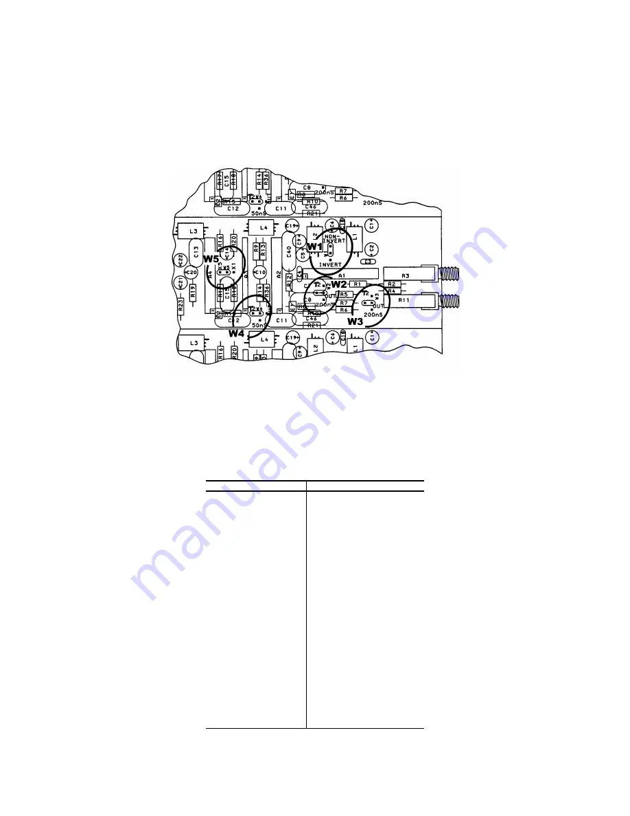
4
Fig. 4.1. Jumper Selection Settings.
Pin
Function
Pin
Function
1
+3 V
23
Reserved
2
- 3 V
24
Reserved
3
Spare bus
25
Reserved
4
Reserved bus
26
Spare
5
Coaxial
27
Spare
6
Coaxial
*28
+24 V
7
Coaxial
*29
- 24 V
8
200 V dc
30
Spare bus
9
Spare
31
Spare
*10
+6 V
32
Spare
*11
- 6 V
*33
117 V ac (hot)
12
Reserved bus
*34
Power return ground
13
Spare
35
Reset (Scaler)
14
Spare
36
Gate
15
Reserved
37
Reset (Auxiliary)
*16
+12 V
38
Coaxial
*17
- 12 V
39
Coaxial
18
Spare bus
40
Coaxial
19
Reserved bus
*41
117 V ac (neutral)
20
Spare
*42
High-quality ground
21
Spare
G
Ground guide pin
22
Reserved
Pins marked (*) are installed and wired in ORTEC’s 4001A
and 4001C Modular System Bins.
Bin/Module Connector Pin Assignments For Standard
Nuclear Instrument Modules per DOE/ER-0457T.
using jumper W5, and is inverting. The 863 is
shipped with W5 in the 5× position.
The output driver stage is hybrid amplifier A5. This
amplifier can drive ±5 V into a 50
Ω
load impedance.
Overall dc-stability of the output level of the 863 is
provided by a continuous baseline restorer. The
operational amplifier, U1, is connected as an
integrator and feeds back the dc value of the output
voltage to amplifier A1. The nominal voltage gain of
the output driver stage is 10× noninverting.
Содержание 863
Страница 6: ...vi ...


