


Spectratime mRO-50
Spectratime mRO-50
1. Introduction
Spectratime used its 25 years of experience in manufacturing ultra-stable Rubidium oscillator for ground and space
applications to produce a miniaturized Rubidium Oscillator (mRO-50) with dimensions, packaging and pinout of crystal
oscillators (OCXO), measuring 50.8 mm x 50.8 mm x 19.5 mm. It delivers a square reference signal at 10 MHz (0 to 3.3 V)
with outstanding performances for a steady power consumption below 0.45 W at room temperature.
Such frequency references are well suited for applications demanding low power consumption, accuracy and retrace, high
frequency stability and low frequency drift such as telecom and mobile network synchronization (TDM, PTP), oil and gas
sensor-based exploration, navigation or timing instruments.
The mRO is described in this document divided into 4 chapters:
• A brief introduction
• A simple description of the principle of the clock
• The specifications of the system
• The operation manual
2. mRO system description
2.1
Principle of operation and basic configuration
The mRO is a miniature rubidium clock and essentially consists of a voltage-controlled crystal oscillator (VCXO) which is
locked to a highly stable atomic transition in the ground state of the 85Rb isotope. While the frequency of the VCXO is at
the convenient standard frequency of 10 MHz, the rubidium clock frequency is at 3.036 GHz in the microwave range. The
microwave signal is directly generated with a second voltage-controlled oscillator (VCO). The phase-stable link between
the two oscillators is established with a fractional-N PLL (phase-locked loop).
The rubidium atoms are confined in a vapor cell at an elevated temperature. The cell is placed inside a cylinder with a gap
to which the microwave power derived from the VCO is coupled. The 85Rb atoms in the cell occur with equal probability
in the two hyperfine energy levels of the ground state 5S (F=2 and F=3).
In order to detect the clock transition between these two levels, the atoms need to be manipulated in such a way that
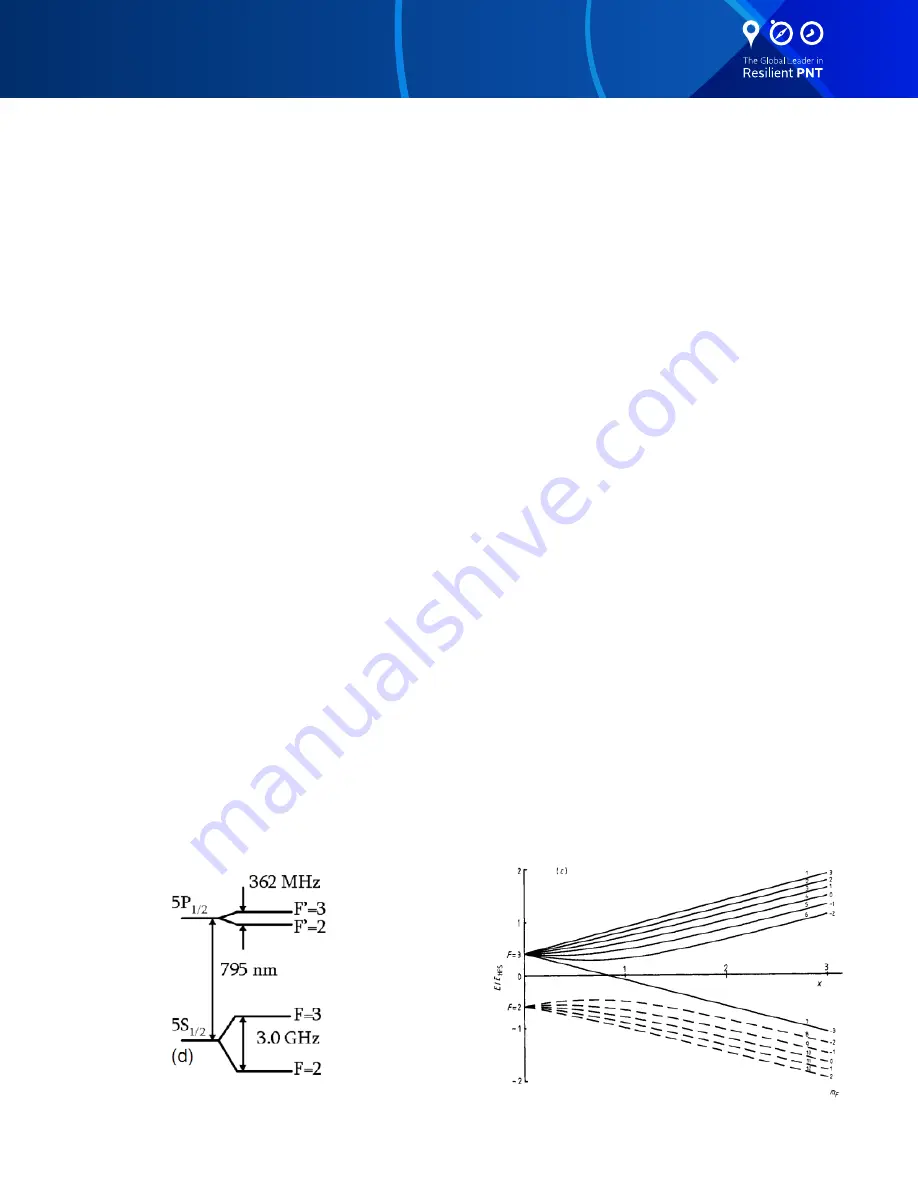
most of them occur in only one level. This is done by optical pumping via a higher lying state (5P). Figure 1 shows the
atomic energy levels and transitions involved in the optical pumping process on the D1-line at 795 nm.
Figure 1: 85Rb optical pumping (D1 line)
Figure 2: The C-field (static magnetic field) splits the Zeeman levels of
the 85Rb hyperfine ground-state 5S. The clock transition between the
mF = 0 levels is only second-order sensitive to the applied magnetic field.


