15/34
HOW TO ADJUST STANDY
THE STANDER IS ADJUSTED IN THREE PHASES AND MUST BE PERFORMED UNDER
THE DIRECT SUPERVISION OF THE SPECIALIST WHO PRESCRIBED IT.
1
st
PHASE: YOU MUST MEASURE:
1. the person's height from below the chest to the ground,
which must be used
to position the chest support.
2. the distance from the kneecap to the ground,
which must be used to position
the stander's kneepads
The measurements can be taken with the person standing or lying down.
2
nd
PHASE: INITIAL ADJUSTMENT WITHOUT THE USER
Transfer the measurements made in phase 1 to the stander
3
rd
PHASE: SUBSEQUENT ADJUSTMENT WITH THE USER
Check:
1. that, once closed, the back support is located in the centre of the buttocks
.
The height of the
arm support
will depend on the positioning of the rear pelvis
thrust cushion
2. the positioning of the kneepads
3. the positioning of the heel stops
in width and depth
4. the position of the thoracic support
5.
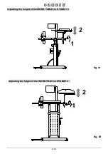
the position of the tray,
which must be set by checking the user's height from
under the elbow to the ground (minimum height). In those cases where it is not
possible to take this measurement with the person standing, measure the dis-
tance from bent elbow to feet with the user lying down.
To operate the handle
(STANDY 4 only) the tray must be moved away.
6. the vertical alignment of the thorax and the pelvis
(any lateral deviation can
be corrected with accessory 857, see pages 25 and 26)
7.
the flexion of the limbs: the standing position is determined by the front-to-
back adjustment of the cback support, kneepads and heel stops
ATTENTION:
ALL ADJUSTABLE ELEMENTS MUST BE LOCKED!!!
MAKE SURE THAT ALL THE ADJUSTMENTS ARE SECURELY LOCKED IN PLACE TO
AVOID SITUATIONS OF DANGER FOR THE USER.
WARNINGS:
THE ADJUSTMENTS MUST BE CHECKED BY THE PRESCRIBER AND REHABILITATION
THERAPIST WHEN CONSIDERED APPROPRIATE TO OPTIMIZE THE STANDING
POSITION, BECAUSE ADEQUATE USE AFFECTS THE PERSON'S FLEXION AND
DECREASES HIS/HER RIGIDITY
Содержание STANDY 3
Страница 2: ......
Страница 4: ......
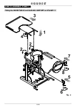
Страница 16: ...13 34 HOW TO ASSEMBLE STANDY fig e Fitting the WORK TABLE and the BACK SUPPORT on STANDY 3 ...
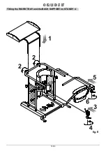
Страница 17: ...14 34 fig E Fitting the WORK TRAY and the BACK SUPPORT on STANDY 4 ...
Страница 23: ...20 34 fig L Adjusting the HEEL STOPS on STANDY 3 and STANDY 4 ...
Страница 30: ...27 34 4 WHEEL SET 861 on STANDY 3 M12X30 SCREW PLUG fig r ...
Страница 31: ...28 34 4 WHEEL SET 861 on STANDY 4 M12X30 SCREW PLUG fig R ...
Страница 32: ...29 34 HEADREST 865 on STANDY 3 fig s ...
Страница 33: ...30 34 HEADREST 865 on STANDY 4 fig S ATTENTION Remove the handle before mounting the headrest page 24 fig P ...
Страница 34: ...31 34 FRONT FOOT RESTRAINTS with BELTS 902 on STANDY 3 BLACK Ø8 WASHER Ø8 WASHER M8x35 SCREW fig t ...
Страница 35: ...32 34 FRONT FOOT RESTRAINTS with BELTS 902 on STANDY 4 BLACK Ø8 WASHER Ø8 WASHER M8x35 SCREW fig T ...
Страница 36: ......
Страница 39: ......


